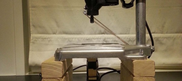
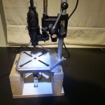
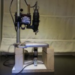
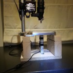
So eventually I decided to do something about it and built this jig. I already had a drill-stand for the Dremel. So I just built a platform that would lift the stand up enough that I could mount a camera underneath it, pointing up through the hole where the drill bit comes down.
At the first attempt I elevated the drill-stand 34mm and stuck a small webcam that I stripped the foot from under it. It looked nice and was practical since it did not take much space. But it did not work very well. The webcam had a built-in LED light so seemed like a perfect candidate for the job. Bolt it in, plug it to a PC, and go. But the built-in light turned out to be useless since it caused some weird reflections in the “tube” between the camera and the PCB. And the contrast became very poor. By creating my own lights with LED strips I got a kind-of usable image, but I was never happy with it.
The camera seemed to be very confused by the reflections coming off the shiny copper and turned it’s shutter time way down. So you had a couple of bright spot where there was reflections, but the rest was very dark. I could not control the shutter time or contrast. Only the brightness. And increasing the brightness made the picture better, but with very low contrast.
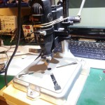
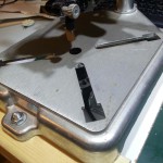
Here is a couple of pictures of the first version:
On the normal image coming from the camera it was very hard to see the drill mark in the pads. But it had several effects that could be applied to the image, and with the “emboss” effect it was much easier to see the different features of the PCB. But it did not feel very reliable since the contrast was so low that any kind of spot in the image could mess with the embossing algorithm. This is how it looked with the emboss effect on.
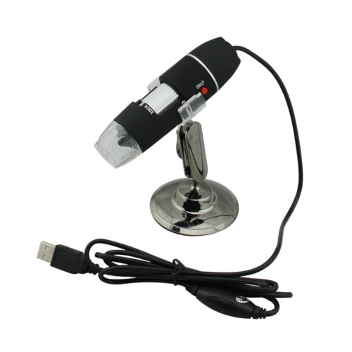
Since I was not happy with the image quality of this setup I started to look for alternatives. And I did not have to look further than over my right shoulder. There I had one of those cheep digital 200x microscopes from China that you hook to the USB port of a PC. Before I started the project I considered the microscope, but turned it down due to the extra height it would add. And the fact that I would be one microscope short in my toolbox if I stole it for this project.
But after the disappointing results with the el-cheapo webcam the microscope was back in the game. I did some tests by just holding it under the drill-stand and looking at the picture stream. And the results was really good. The microscope also have a built-in light. And the LEDs are closer to the lens and more evenly distributed around it than the webcam. And due to the high magnification the “tube” going up to the PCB could not be seen in the picture at all, so any reflections from it did not affect the image. And this camera did not get confused by the bright spots on the copper.
The major increase in quality made the extra height seem well worth it. And the problem with lack of microscope in toolbox was easily solved by buying another one. This time I bought a 500x microscope with 8 LED illumination. I tried this for the jig as well, but it did not give any significant improvement over the old one. But it give a much better image when actually using it as a microscope. So I was happy all around.
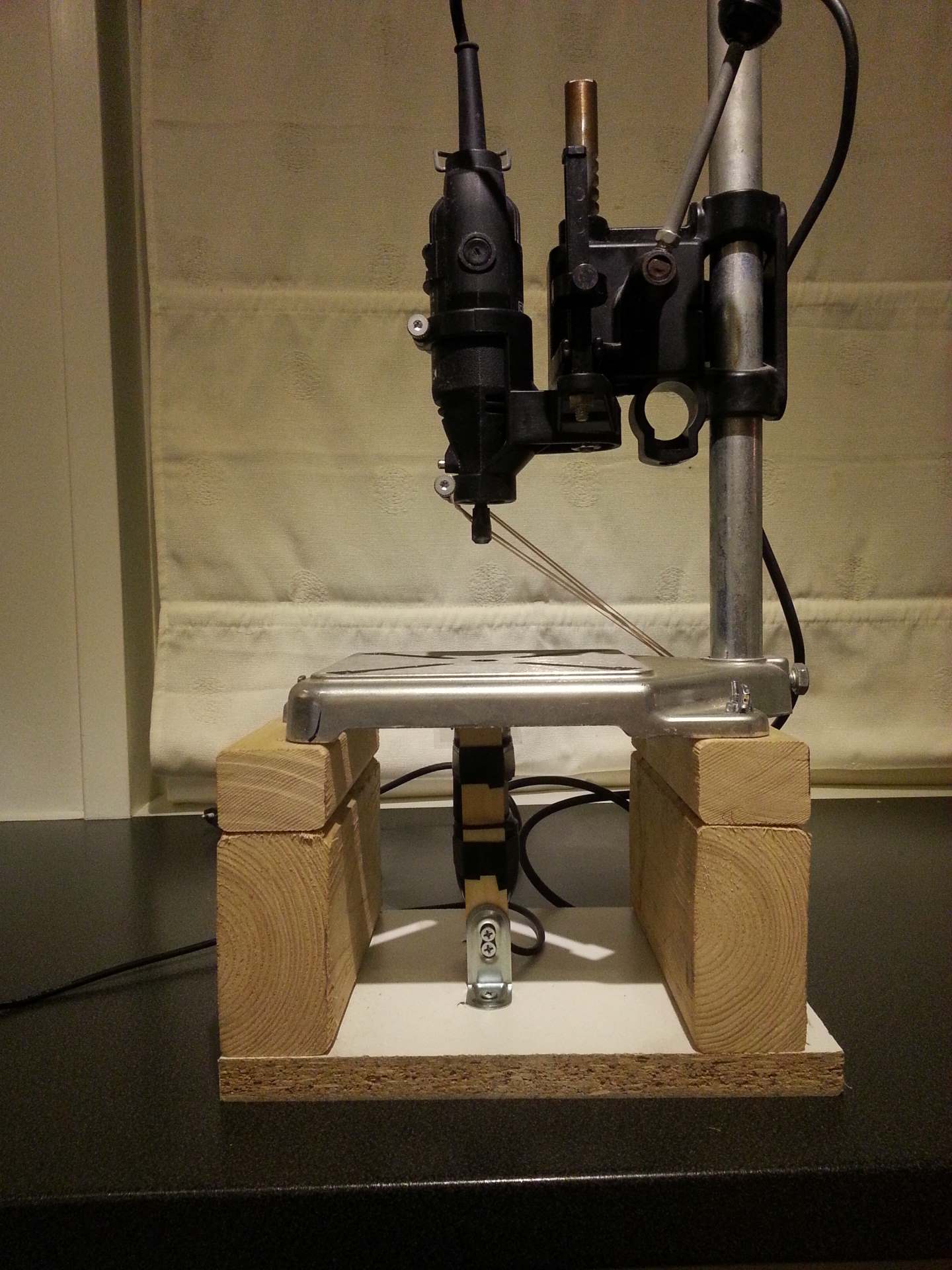
Now that the decision was made I modified the original platform to accommodate the height of the new camera. Adding two 95x46mm wood rails under the original 34x45mm rails gave it the perfect height. And I did not have to do anything about the bolts embedded in the original rails for fixing the drill-stand on top of the platform.
Then I removed the short and wide metal angles I had used to mount the webcam and replaced them with two narrow but higher metal angles that would hold to wood struts vertical with just enough space between to fit the camera. I then simply stuck the camera in between the two and taped it in place with electrical tape. Then I wrapped a small zip tie over the focus adjustment wheel (the silver colored part of the camera. The reason for this is that the focus mechanism is quite sloppy on these cameras. And it feels like there is something rubbery inside. So when you have adjusted it to perfect focus and then let go, it will slide back slightly and fuzz up the image. By adding the zip tie with just the right tension both these problems went away.
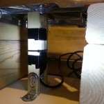
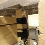
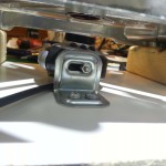
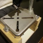
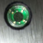
This is how it looks from above. The second image is a closeup down the base plate of the drill-stand into the camera lens. It is hard to tell from the image, but over the lens I have put a small piece of clear plastic to prevent debris from the drilling action to fall into the camera. The plastic is just bent in a U shape over the lens and held in place by the two wood beams the camera is attached to. This gives it a slight curve that help the debris to slide off it. And it makes it very easy to replace if it should ever be scratched up by the fiberglass nastiness falling onto it.
How does it work?
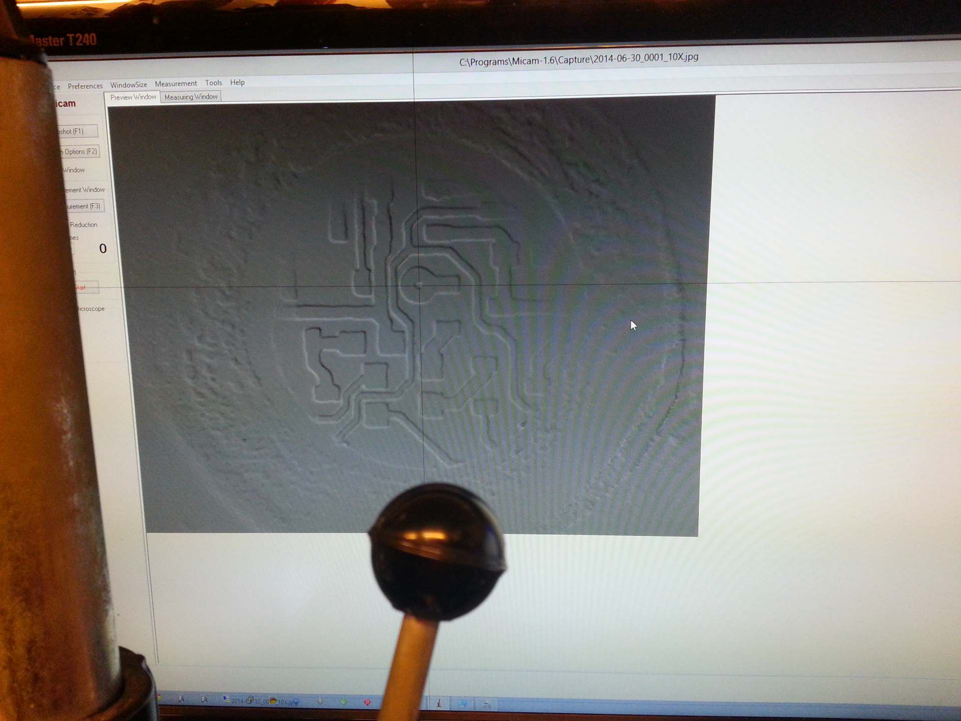
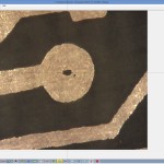
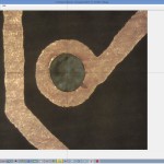
Before each use the jig first has to be calibrated. That is easily done by drilling a hole in something. A piece of paper, some scrap copper clad, or if the PCB is not cut to perfect size yet, just drill a hole in a part that will be trimmed away. Then place a cross hair in the center of the newly drilled hole. Being careful not to move anything before placing it. After that it is just a matter of aligning the drill mark of each pad with the cross hair and drill. I get very close to perfect placement every time. Below are a couple of screenshots showing how it looks on the PC while drilling. The first image is of a pad with only the etched drill-mark in the copper. The second show a pad that has been drilled.
To capture images and video from the camera I use [Micam]. It is free (but you can donate if you find it useful) and works great with these USB based microscopes. Unfortunately Micam does not have built-in support for a cross hair. So I use another utility for that called [CrossHair] (bet you didn’t see that coming!). This utility is also free and is perfect for this task but unfortunately considered obsolete by the author. But as long as it keep running on the windows version in use there is no need for an update as it works perfect for marking the drill position as it is.
CrossHair is controlled by two global hotkeys. One toggle the cross hair on and off in roving mode where it will follow the mouse cursor and allow you to place it over the center of the test hole you make. Then you press another hotkey to freeze the position of the cross hair so it don’t move if you bump the mouse.
Perfect! Now you have an easy way to mark the exact location where the drill-bit will break through the PCB. Or rather the exact location where it broke through when you drilled the test hole. The Dremel drill-stand is not the most stable construction ever made and have a bit of slop in it. But by making sure it is always slopping in the same direction each time the precision becomes pretty good. To achive that I have added some rubber bands that holds it in the position it wants to move when I start dragging the lever (see the pictures). And by pulling the lever in similar direction and with similar force each time.
I might try to modify the stand at some point to allow foot pedal control. Either by using a bicycle-brake kind of wire or an electric servo motor. That would make all forces be local to the stable part of the stand and should give even better repeatability. If it happens you will read about it here 🙂
If you happen to know about a non obsolete cross hair utility that could work for this project, please let me know!
I have now developed a dedicated application to work with the jig. More info to be found here.
Great tutorial!
Instead of worrying about a cross hair utility, I would print one on a clear acetate with a circle about the size of the pad as it appears on-screen and would hold it tape it in place on the monitor or TV. The circle pattern should help to a finer centering.
How would you make the acetate move around on the screen as you move the PCB over the camera? And I think my printer would have issues printing any thing the size of a regular sized PCB zoomed in 200 times 🙂
Pixmicro solves both those problems with a lot less fuss.
The hotkeys I mention here is for the Crosshair utility I used before I developed Pixmicro. It had two user configurable global hotkeys for toggling the crosshair on of (that I used to bind to CTRL+ALT+Z) and another that would freeze it so it no longer followed the mouse (that I used to bind to CTRL+ALT+X). Now that I have Pixmicro I do not use that utility anymore.
What are the two global hotkeys you mention in relationship to crosshair above?