Spektrum satellite based wireless RC simulator link
If you had a look at my workshop page you have probably realized that I’m into RC helicopters. And a good way to get a bit of training on a rainy day is to use a helicopter simulator.
Most RC flying simulators allow you to connect your regular RC transmitter to the PC and use it to control the virtual model. What makes this possible is the fact that most RC transmitters have a “trainer port” that is used for connecting a student transmitter to a teacher transmitter. This allows the teacher to give control to the student by pushing a button and take it away when the student loose control by releasing the button (and then take credit for the crash). When the button is pushed the teachers transmitter transmit channel data from the student transmitter.
Since when a transmitter is in “student mode” it will send it’s channel data through the trainer port rather than over the air, and since the protocol used is fairly standard, it is fairly easy for the RC simulator developers to create a little hardware device that convert the channel data transmitted on the trainer port to something that can be read through a USB port.
The only commercial simulator I have ever owned is Phoenix RC, and it comes with a “USB dongle” with two wires. One that hook into a USB port on the computer and another that hook into the trainer port on the transmitter. But I have also played around with free simulators that allow you to connect the trainer port to your sound card input and that decodes the signal that way. Either way it works really well. The only problem is that you have to tether your transmitter to your PC with a cable.
Which is annoying. You have this piece of hardware that is specifically designed to provide wireless control, and here you are stuck with a wire. So for a very long time I have wanted to make a device that would allow me to get rid of the cable.But it never reached the top of my todo list. Until now.
Since the device is now built I figured I would make a writeup about it.
Prototype
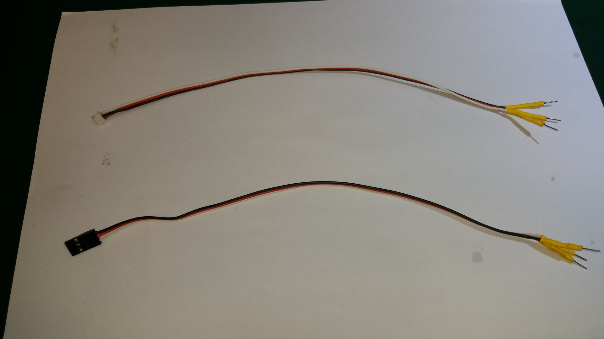
To figure out the spektrum serial protocol and test the rest of the hardware I made a prototype based on an ATmega328 breakout board that I made earlier for just this kind of testing. I started by maing two wires that both had dupont male connector pins in one end. In the other end the first cable had a JST-ZH-3 for plugging into the data port on the satellite receiver and the other had a servo plug for plugging into a channel on a regular receiver.
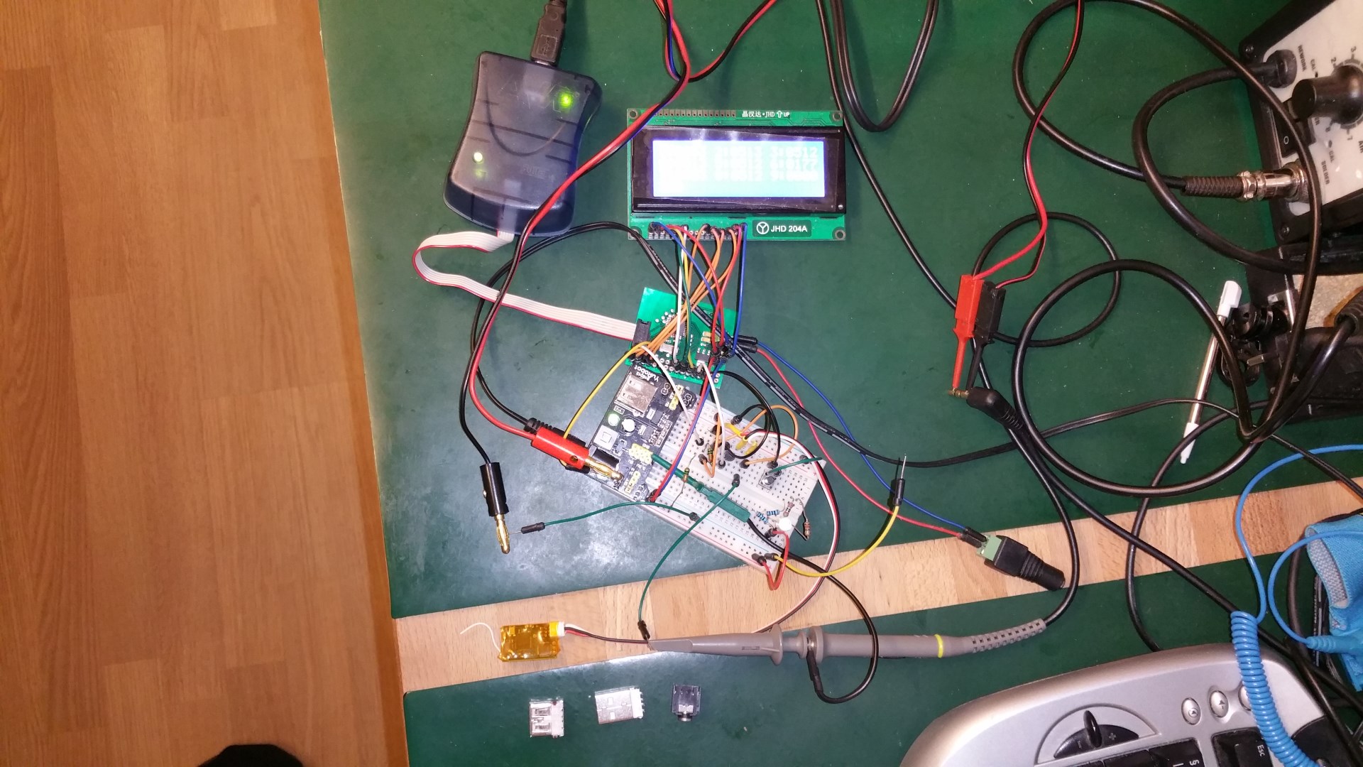
 The bread board held the power supply unit, a bidirectional 3.3V <-> 5V level converted made of a MOSFET and two resistors, and another MOSFET for allowing the MCU to turn power on/off to the satellite receiver.
The satellite receiver was connected to the 3.3V power rail and the LV side of the level converter using the fore mentioned JST-ZH terminated cable.

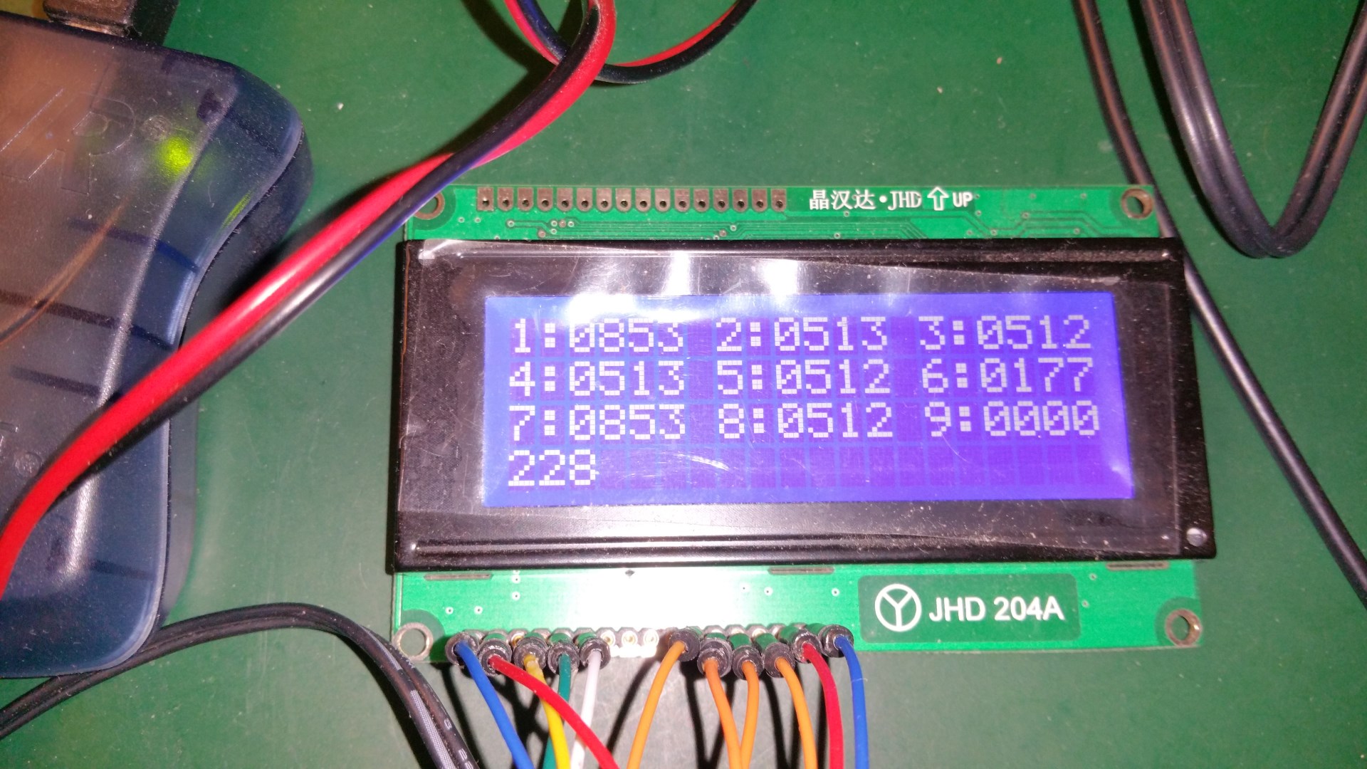
A bit later in the process I removed the LCD display and replaced it with an RS323-TTL -> USB converter hooked to the MCU USART-TX pin. The display was convenient for debugging, but was not something I would include in the final version. So I switched to debugging over a serial port. The ATmegaXX8 MCUs only have a single USART unit. And one is needed for the communication with the satellite. Luckily though, only the RX part is needed for that so I used the TX line to send debug information to the PC. The final version have the USART TX pin wired along with GND to a two pin connector that can be used for firmware debugging.
The hardware
After I thought I had figure out everything that needed to be figured out using the prototype I made the final schematics and routed a board in DipTrace. Then I fabricated the PCB like outlined here. Since it has the form factor of a USB pen I tried to make the PCB as small as possible. But I did not want to use SMD connectors out of fear of having them ripped off the board. And I wanted to be able to continue developing the firmware in a convenient way on the final device, so I included an In Circuit Programming (ISP) connector and a two-wire serial-out connector for programming and debugging.
The final size of the PCB was 60mm x 20mm. I would have liked to have it smaller, but didn’t want it bad enough to spend any more time trying to shrink it. I put all the through hole components on the top side and all SMD components on the bottom side. I wanted to turn the ISP connector 90° to make the board shorter, but since the pins go through the board I could then not find open space large enough for the MCU at the bottom side of the PCB.
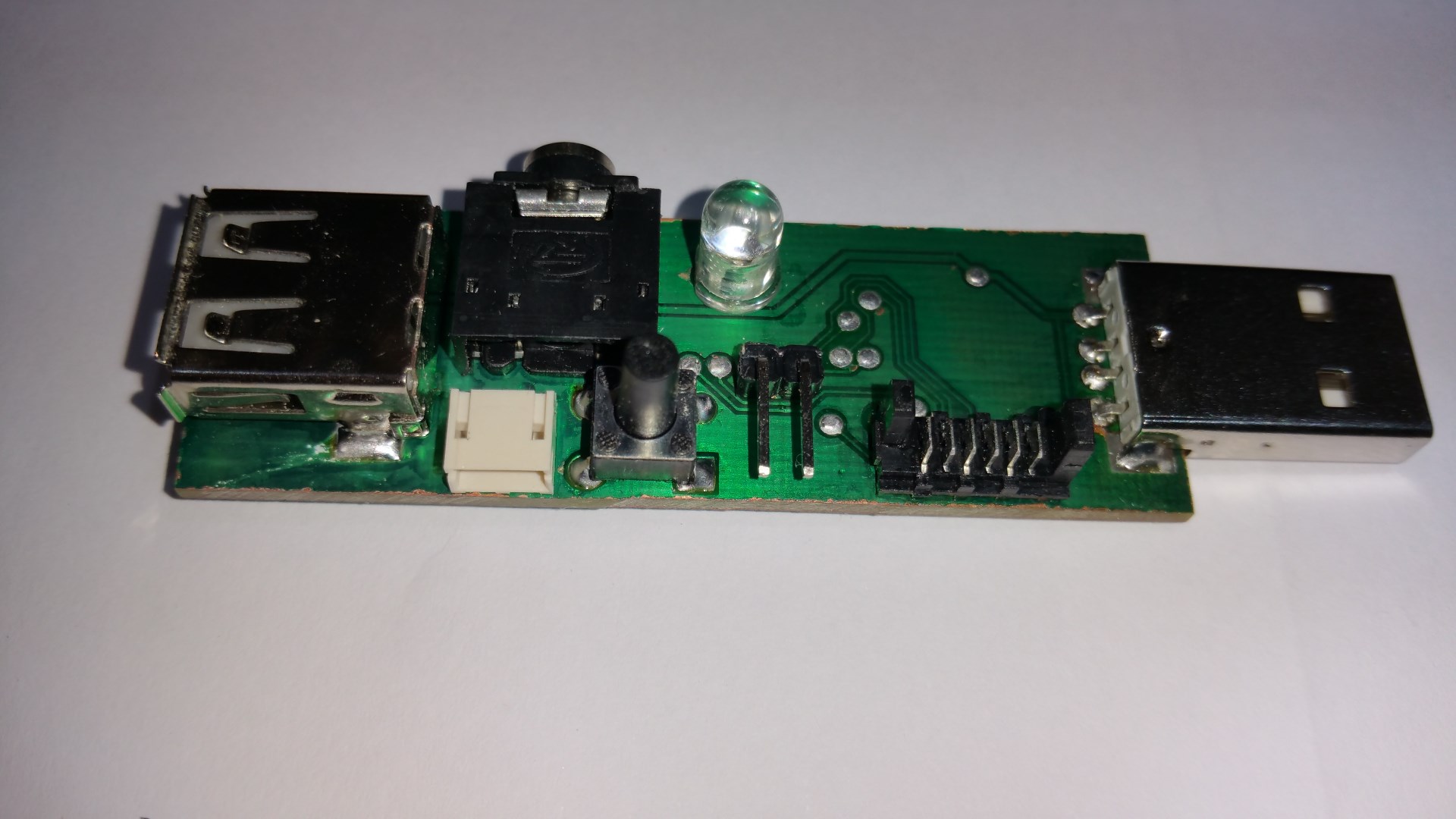
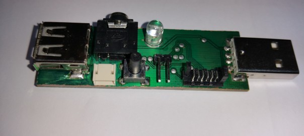
The top side of the PCB contain all connectors and user interface components. From the left you see:
- USB female connector for pass through of the USB data and power lines.
- 3.5mm headphone connector for PPM out.
- 3-pin JST-ZH connector for the satellite receiver.
- Micro switch used to initiate the receiver<->transmitter binding process.
- RGB LED for user feedback.
- Two pin header connector for serial out.
- 6-pin Picoflex™ ISP connector.
- USB male connector for powering the board and passing through to the female connector.
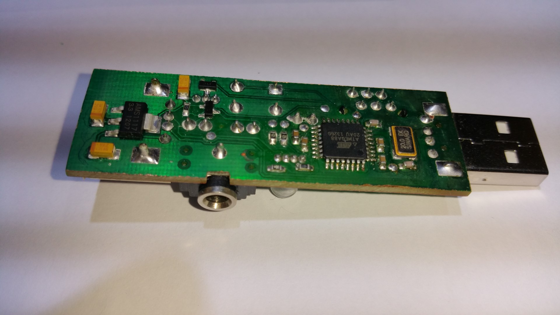
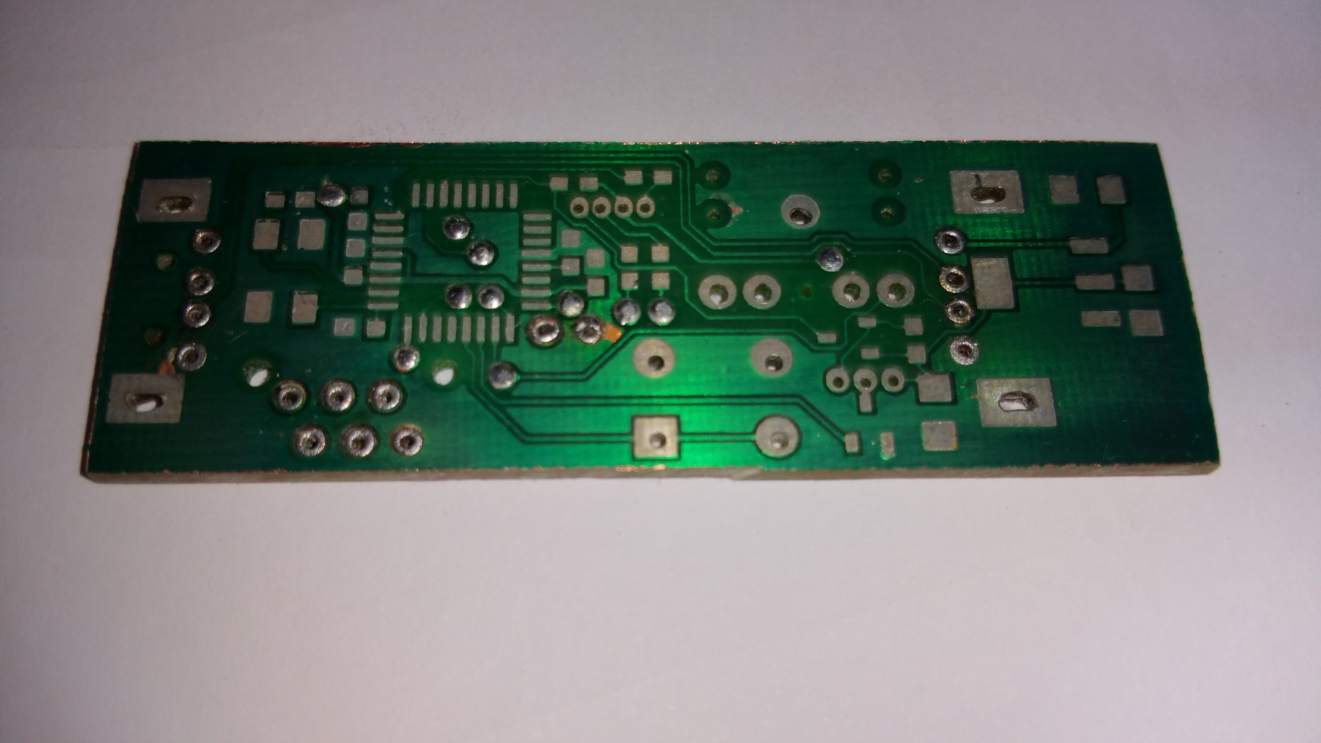
The bottom side hold the MCU, 20MHz crystal, 3.3V LDO, and a few other components for providing filtering, bypassing, level conversion, and satellite power switching. For the prototype I used an ATmega328 but for the final version I used an ATmega88. Both are a bit overkill for the project, but the ATmega88 are very cheap and have all the peripherals needed. And I have a bunch of them. So that’s what I decided to use. Where I to make a lot of this I would probably have searched a bit deeper to see if another chip might be more economical.

This is how it looks when hooked up and in use. Here I use an USB extension cable to connect it to the PC but it is also possible to stick the SimLink directly into the PC.
The USB connectors
Since the SimLink is meant to provide output to a USB device hooked to a PC it made sense to power it from a USB port. And to avoid taking up an extra USB port simply to power the device I added a female USB connector to the other side of the board and routed both signal and power through to it. So now you can connect the SimLink to an USB port and then hook both the USB and signal wire from the simulator dongle to the SimLink and not use any more USB ports on the PC than before.
The satellite port and bind switch
Input to the SimLink comes from a Spektrum compatible satellite receiver. It works fine with both the genuine Spektrum satellites and the Orange RC Spektrum compatible satellites (the one shown in here). Since USB power is 5V and the satellite need 3.3V the SimLink have a 3.3V LDO linear regulator on board. I still run the MCU on 5V though to be able to run it at it’s maximum speed of 20MHz. So a bidirectional level converter is needed on the satellite IO line.
For the satellite to work it first has to be bound to a transmitter. In the early prototyping stages I just connected it to a regular receiver and bound it that way. But later on I implemented binding support into the SimLink. Binding mode is initiated by sending a series of pulses to the satellite over the IO line during a small window after power has been applied where the satellite have the IO line programmed for input and are listening. After this window the IO line becomes an output from the satellite and it is not possible to enter binding mode any more.
For the regular receiver this is working fine. You plug in a “bind plug” to the main receiver and then power up the system. The main receiver see the bind plug and put the satellite in bind mode. But for the SimLink I thought it would be much more convenient to be able to start the binding process without having to unplug it from the USB port and then plug it in again. So I added a “bind switch” to it that can be pushed by the user to start binding and a MCU controlled power breaker for the satellite. So now the MCU can power cycle the satellite and put it in bind mode at any time without removing power from the whole device.
Thus the whole satellite interface looks like this:

R1/R2 and Q1 acts as a bidirectional 3.3V <-> 5V level shifter (VCC is 5V). Pin 3 of the connector is the satellite IO line and the net labeled “Satellite IO” go to the USART-RX pin of the MCU. I was hoping to be able to remove R2 and solely rely on the built-in pull-up in the MCU, but the internal pull-up was to large and could not achieve the rise times needed.
Q2 is the satellite power switch. For simplicity I use an N-CHANNEL MOSFET on the GND side. Which works fine as long as the MCU put the IO line high before cutting the power.
The PPM output
The simulator dongle normally connect to the trainer port of the transmitter using a 3.5mm audio jack. So the SimLink have a female 3.5mm audio jack for output. The trainer port signal is a PPM (Pulse Position Modulation) encoded channel train.
The signal idle high and all channels are transmitted every 22mS with a train of 400uS negative pulses. The value of each channel is defined by the time between the pulse at it’s position in the train and the previous pulse. The minimum value is 0.9mS and the maximum is 2.1mS. So with a 9 channel transmitter the max time it can take to transmit all channels is 2.1ms*9. So 18.9mS. That leaves a 3.1mS gap between frames and is the absolute maximum number of channels that can be transmitted with a 22mS frame size and still be able to tell where each frame start.
While the timing of the PPM signal seems to have been pretty well standardized (makes sense since it matches the standard servo PWM timing) the voltage level is highly brand specific and vary widely. It seems like levels all the way from ~1V to ~12V is used. Even the different Spektrum models seems to vary between ~3 and ~12 volts.
So the PPM output of the SimLink is just connected directly to one of the PWM outputs of the MCU giving a signal with ~5V PP. And that works just fine with the Phoenix R/C dongle. And I guess it should work fine with any other dongles that support a wide range of transmitters.
The RGB LED
The only form of output to the user is though a 5mm RGB LED. The ATmega88 MCU have 6 PWM outputs. And one of them is used for generating the PPM signal. So that leave 5 free, and I hooked 3 of them to the RGB LED. The ATmega88 outputs can easily supply the 15mA I wanted for each color in the LED so they are simply connected to the MCU through current limiting resistors.
If you wondered why I wrote “after I thought I had figure out everything” and not simply “after I had figure out everything” in the beginning of this section, here comes the answer.
The ATmega88 have 3 timers. Two 8-bit and one 16-bit. And each timer have two output compare registers that can be used to produce a PWM signal. Hence the 6 PWM channels. I did not actually prototype the LED part before building the real thing. And I made the mistake of using the two PWM channels of the first 8-bit timer for two of the LED’s cathodes and share the two comparators on the second 8-bit timer between the third LED cathode and the PPM output. The idea being that I wanted to leave the 16-bit timer completely free for timing purposes.
But what I had not realized was that the two output compare units associated with a timer was not 100% independent. The compare value can be set individual, but the waveform generator mode is shared. And the mode had to be different for the output generating the PPM signal for the main output, and the one generating a PWM signal for the LED. Bummer! So in the end it turned out that driving the LED of one of the 16-bit compare units would have worked just fine (the period time I ended up using for it would have worked fine for the LED) but driving it from the same timer as the PPM output would not.
Luckily the MCU has enough omph that doing the PWM for one of the LED colors in software from a timer overflow interrupt worked out just fine. I wish I had prototyped the LED though, and if I’m going to make more of this device I’m probably going to change it.
Programming / Debugging
To be able to upload and debug the firmware there is an ISP connector and a 2-wire serial connector on the board. To save space I used a 1.27mm pitch Picoflex™ connector rather than the standard 2.54mm pitch 2×3 header pin connector used for programming the Atmel chips. The serial port is connected to the same USART that is used for receiving data from the satellite. So debug output has to run at the same baud rate and frame format as the satellite. Which is 15200 8N1. So that is working just fine.
The firmware
The firmware is not 100% done yet, but it is complete enough to let me fly wirelessly on the sim. And that might be a big obstacle for further progress 🙂
The main responsibilities for the firmware is:
- Configure all IO pins and peripherals.
- Read serial data from the satellite and decode the channel data.
- Produce a PPM signal from the channel data.
- Control the RGB LED and give user feedback through it.
- Monitor the bind switch and put the satellite into bind mode if it is pushed.
The firmware have multiple threads of execution. The first is the main timer interrupt. The 16 bit timer run directly off the CPU clock (20MHz) and is set to trigger an interrupt and reset at 1000. So the timer interrupt is trigged 20000 times per second. This timer interrupt update the PWM signal to the red catode of the LED every time it is trigged. So with 8-bit PWM the PWM frequency is ~78Hz. It also increment a counter and each time this counter reach 20 it is reset and the system clock is updated.
The system clock track number of milliseconds that has passed since bootup (or last wrap) in a 32-bit integer. This is used for any timing needed for the rest of the firmware (like detecting if the framerate is 11mS or 22mS, timing fading effects on the LED, etc etc).
The second thread of execution is the USART RX interrupt. Whenever a complete byte has been received this interrupt trigger and process it. It use the real time clock to see how long it has been since the previous byte was received, and if it is longer than 6mS it assumes that the byte is the first byte of a new data frame. It do some basic processing of the data and store raw 11 bit channel data for the first 9 channels. When 16 bytes has been received it will increment a “frames received” counter. If more than 16 bytes is received before the next pause in the stream, something has gone wrong and the extra bytes are ignored.
The third thread of execution is the interrupt from the timer used to generate the PPM output.
The fourth thread of execution is the main loop of the program. It monitors the “frames received” counter and every time it increments (or every second for 11mS frame rate) it will convert the raw 11-bit channel values to “length of low pulses” in timer clock cycles and start a new PPM pulse train. Or if too long time has passed since the last frame was received it will change the LED color from slow green pulsing to quick red pulsing. It also monitor the bind switch and goes into the receiver binding procedure if the switch is pushed.
Reading data from the satellite
The protocol from the satellite is very simple, but I’m still lacking some essential information to fully decode it. The current version of the firmware can decode both 10-bit and 11-bit channel data, but it can not automatically detect which format it is receiving.
The data from the satellite is transmitted asynchronously at a baud rate of 115200, 8 data bits, 1 stop bits, and no parity. So the entire hardware layer short of the signal level converter is built right into the ATmega88 through it’s USART unit.
The Spektrum Satellite protocol
The protocol on top of this use 16 byte frames that is transmitted either every 11mS or every 22mS depending on the DSM version and various other factors. Each frame start with a 2 byte header followed by 7 channels occupying 2 bytes each.
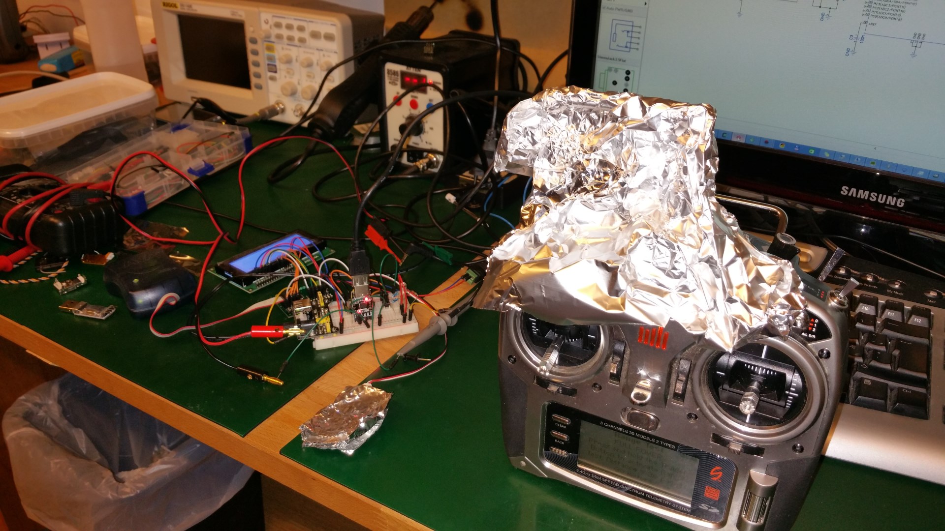
The first byte in the header is a frames-lost counter. Googling told me that some or all bits where used for the counter, but I could not find a definite answer to how many bits where used, and to whether there might be more information in this byte. So I decided to figure it out.
I started by wrapping the receiver in tin foil to prevent it from hearing the transmitter. But with the transmitter right next to it, that was not enough. So I wrapped the antenna of the transmitter as well. But that was still not enough when the transmitter was sending at full power. So then I put the transmitter in “range check mode” where it transmit at reduced power. And now I could provoke frame losses by manipulating the tin foil wraps.
So this exercise taught me that all 8 bits of the first byte was used for the lost frame counter. And that it would stop at 0xff even if more than 255 frames was lost. And it proved that if the governmental mind control devices use 2.4GHz at low transmitting power a tin foil hat will actually work. At least if you are able to also wrap the mind control device.
The second byte in each frame probably contain information about how the rest of the frame is formatted. I have found various information on the net, but nothing that match what I see from my satellites. I hope that this byte hold information about how many frames are needed to receive all channels, and how many bits are used for each channel. But so far I have not been able to decipher it. If you happen to know anything about this, please shoot me an email!
After the 2-byte header comes the channel data. Each channel use 10 or 11 bit for the channel value, 4 or 5 bits for the channel ID, and 1 bit for marking the first channel in the second frame if multiple frames are used. So when you know weather 10 or 11 bit channels are used, it is very easy to decode the channel data. But without this information it gets rather tricky.
Here are some tables illustrating how the frames look:
| Lost frame counter | ???? |
| Channel MSB | Channel LSB |
| Channel MSB | Channel LSB |
| Channel MSB | Channel LSB |
| Channel MSB | Channel LSB |
| Channel MSB | Channel LSB |
| Channel MSB | Channel LSB |
| Channel MSB | Channel LSB |
| Byte0 (MSB) | Byte1 (LSB) | ||||||||||||||
| F | C4 | C3 | C2 | C1 | C0 | D9 | D8 | D7 | D6 | D5 | D4 | D3 | D2 | D1 | D0 |
| Byte0 (MSB) | Byte1 (LSB) | ||||||||||||||
| F | C3 | C2 | C1 | C0 | D10 | D9 | D8 | D7 | D6 | D5 | D4 | D3 | D2 | D1 | D0 |
In 22mS mode a maximum of 7 channel can be transmitted and all available channels are transmitted in every frame. In 11mS mode two data frames are used to transmit all channels. So up to 14 channels can be transmitted. If less than 14 channels are transmitted some can be repeated in both frames giving double update rate for those channels.
- The F in each channel seems to be a flag indicating the first channel of the second frame when 11mS mode is used.
- The C bits are the channel ID.
- The D bits are the actual channel data.
Now that the hardware is done I will have a closer look at the protocol and see if I can get it to auto detect the protocol format. I will update the article with whatever I find.
Binding the satellite to the transmitter
For the initial testing I used a regular Spektrum™ AR6210 DMX receiver to bind a Spektrum™ satellite to my DX8 transmitter. I also tried to bind an Orange RC satellite using the AR6210, but that did not work. Which surprised med a bit.
When I had most everything else working I started to look closer into the binding process. There is only 1 IO wire going to the satellite, and it is normally used for transmitting serial data from the satellite to the SimLink. But for a few milliseconds after getting power the satellite will listen for a signal on the wire rather than transmitting. And if it see 3-9 negative pulses on the line during this window it will go into one of the binding modes. I have found conflicting information about what the pulse counts mean on the net.
At [https://gist.github.com/skelly/ef01907a5c90dd66f987] I found this list:
- 2 low pulses: DSM2 1024/22ms
- 4 low pulses: DSM2 2048/11ms
- 6 low pulses: DSMX 22ms
- 8 low pulses: DSMX 11ms
And at [http://svn.mikrokopter.de/websvn/filedetails.php?repname=Projects&path=%2FSpektrum-Diversity%2FSoftware%2Fdiversity.c&peg=938] i found this:
- 3 Pulses: DSM2 10-bit / 22ms
- 5 Pulses: DSM2 11-bit / 11ms
- 7 Pulses: DSMX 22ms
- 9 Pulses: DSMX 11ms
When I captured what the AR6210 did I could see that it waited 192mS and then sent 8 pulses. Which matches DSMX 11mS from the first table. The weird thing though, is that when I try to send it 8 pulses from the SimLink it will not bind. But if I send 9 (same protocol from the second table) it bind as DSMX 11mS.
When I tried to bind the Orange satellite by connecting it to the AR6210 it did not go into bind mode at all. And when hooking it to the SimLink and trying to mimik the AR6210 it would not play either. So I tried to incrementally reduce the delay between power on and the pulse train. And it seems that Orange satellite will not enter bind mode if the delay is much bigger than 50mS.
Since the SimLink provide and control the power to the satellite it can force it into binding mode at any time. When the user press the Bind button the firmware will shut down power to the satellite and make the LED blue. Then it will wait 2 seconds while morphing the LED to red. Then it will turn power back on for the satellite and wait 50mS before sending the bind pulses. This delay seems to work for both the Orange RX and the genuine Spektrum™ satellite
There is clearly more to the binding protocol than what I have figured out so far and I will have to spend a bit more time investigating it. For now I send 5 pulses and decode the received data as 11mS/frame and 11-bit channel data. And that work find with both the Orange satellites I have and the genuine Spektrum™ satellite.
Producing the PPM signal
Every time a new set of channel has been received from the satellite the SimLink will generate a pulse train on the PPM output based on the channel data. To generate the PPM signal I use one of the 8-bit counters running at 1/8th of the CPU clock in “Normal” mode (no PWM mode set). In this mode you can set it to toggle, set, or clear the output compare pin and trigger an interrupt each time the timer match the output compare register.
Since 8-bit is not enough to time the pulses I use an extra byte for counting timer loops. So each time a compare interrupt trigger I decrement the loop counter and check if it reached 0. If it reached 0 I know that on the next interrupt it will be time to toggle the output. So I then setup the timer to do so on compare match. The next time the interrupt trigger the timer HW will already have toggled the output for me, and I can disable the automatic toggling on compare and calculate the number of clock cycles until the next transition.
I store the calculated value in a 16-bit integer. The upper 8 bits will then be what should go into the loop counter and the lower 8 bits tell how much the compare register should be incremented. If this increment is to small the timer might have already advanced past it by the time it has been calculated and the next compare will be missed. So if it is less than 64 I decrement the compare register with 127 instead to make it hit early the first time. On this first interrupt I set the compare register to the actually calculated value, which is then guaranteed to be far enough away from the current counter value to not be missed.
After the last pulse I disable output compare toggling and the timer compare interrupt and wait for the next frame to be ready.