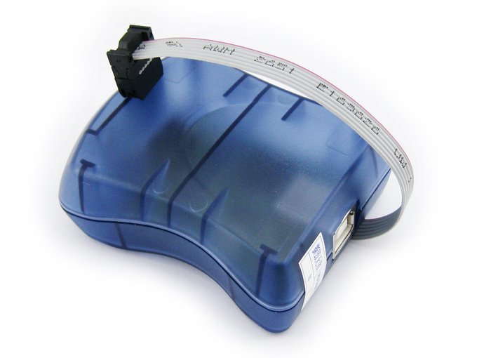
 This is clearly not “the definitive guide to repair any fried AVR ISP programmers no matter what happened”. But rather more specifically how I brought my dead AVR ISP back to life after I first noobed out and fried it.
What killed it was me doing repairs on a live circuit hooked to the programmer that was then hooked to my PC. The circuit had a bad connection on a point connected directly to it’s 12V power supply and I was just going to add a bit of solder to the connection and reflow it. With a soldering iron. An as it turned out, hard-grounded soldering iron. And I forgot to cut the power to the circuit before doing so.
The circuit was powered by a fully insulated 12V power supply. So I guess what happened when I touch the 12V rail with the soldering iron was that I pulled the 12V down to my shops earth-ground. And the circuits GND to 12V below the shops earth-ground. And that is bad news. That GND was connected to the GND of my AVR ISP which again was connected to earth-ground via my PCs USB port. So the equivalent of hooking the negative lead of a 12V power supply to the ISP-GND and the positive lead to the USB-GND on the programmer. It was obvious from the smell that something inside the programmer had let all it’s magic smoke out.
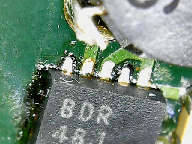
I would have expected that such an exercise would have lead to a fried track on the PCB, but apparently not. When opening the programmer I found that one tiny chip next to the USB connector clearly had reached junction temperatures violating it’s absolute maximum rating and had swollen a bit.
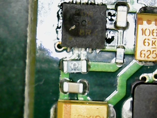
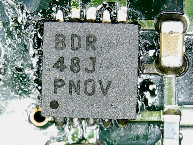
The chip was not so badly mangled that the markings could not be read. But unfortunately the manufacturer had not found enough space on the 3x3mm chip to make the chip identifiable. It said “BDR SCK J8RJ” but googling that did not help. But I found [this thread] where someone else had identified it as TPS61020DRCR. He also told that replacing it had fixed his programmer. So I hunted down the TPS61020DRCR on ebay and decided to have a go at repairing mine.
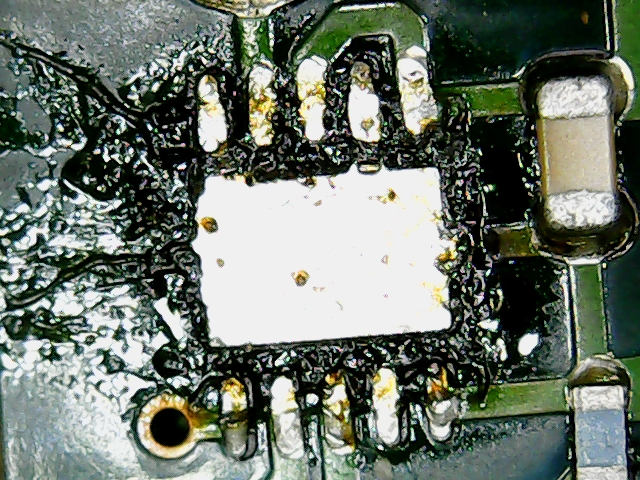
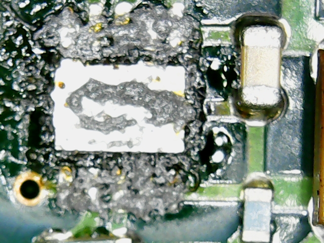
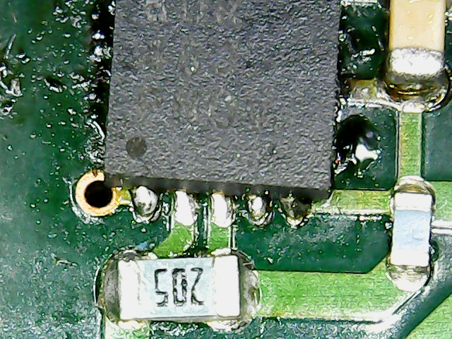
The TPS61020DRCR is a boost converter in a VSON-10 package. This is a 3x3mm no-lead package with 10 signal pads plus a thermal pad. So not something you will get off the board with a soldering iron. But with a hot-air rework station getting it out was no problem. In the first picture quite a bit of solder was left on the pads. In the second I have removed most of it with a regular soldering iron and a solder wick. The gooey stuff around the footprint is flux residues from the solder wick. This is how the PCB looks after removing the chip:

When the excess solder was removed I added a bit of reflow solder paste to the footprint:
And reflowed it using the same hot-air soldering station I used to remove the buckled chip:
Still crossing my fingers hoping that I got a good thermal connection to the thermal pad. But so far everything seems to be fine. The programmer was recognized by the PC again and it talks to my MCUs. So now I have a backup programmer (when it fried I ordered a new one before the magic smoke cleared).