DIY Double Sided 60W LED UV Radiation Unit With Vacuum Pump
Summary
This is a description of how I designed and built my UV exposure box. After experimenting a bit with dry-laminate photo-resist and liquid UV hardened solder mask I decided to stop trying to improve my toner transfer technique and rather build a proper UV radiation unit for making printed circuit boards.
I wanted it to be powerful and compact so I decided to use UV LEDs as the UV source. The preferred wavelength for the LEDs would probably be 365nm, but those LEDs turned out to be hard to find, and very expensive. The 395nm-405nm LEDs on the other hand are very inexpensive. And best of all, can be bough as high-density LED-strip’s on 5-meter rolls. So I bought two “5M Ultraviolet 395nm 3528 SMD LED” rolls that have 120 LEDs per meter for a total of 600 LEDs per roll. From what I could tell from a bit of googling the wavelength should work even though it is not ideal. Initial tests proved that the 395nm LEDs worked very well.
This page (and the unit itself) is still very much work in progress. The CAD files and firmware source code can be found in my github repository.
Features
The UV exposure unit is controlled by an ATmega328P microcontroller and have the following features:
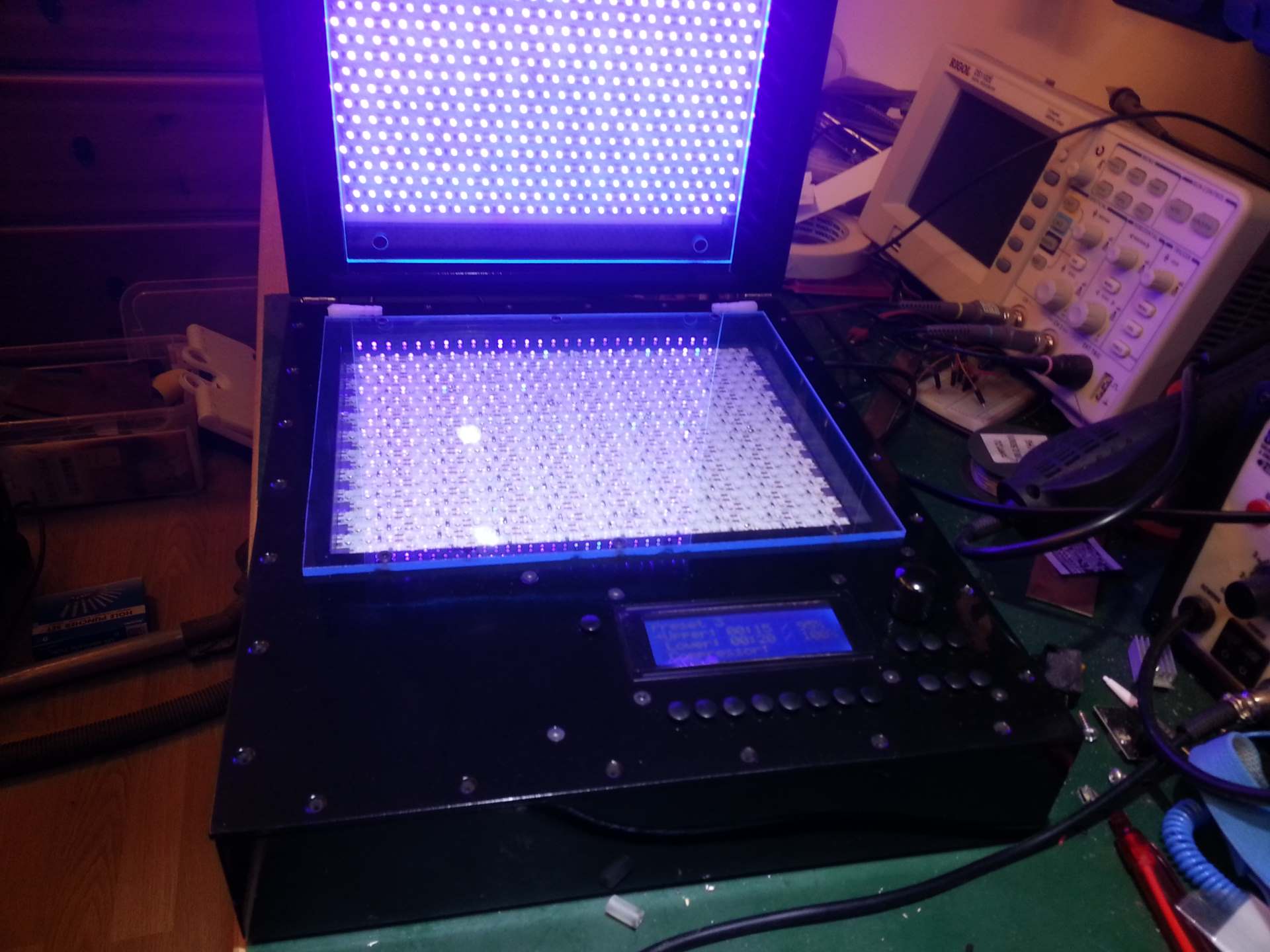
- Single and double sided exposure. Each side radiated by a 594LEDs / 30W UV LED panel (The unit has a total of 1188 LEDs providing 60W of LED light).
- The light panels can be calibrated to give even exposure on both sides.
- Built-in vacuum pump for laminating artwork and copper-clad.
- The user can define 2-18 speed steps for the vacuum pump.
- The vacuum pump can be set to automatically turn off a specified time after the radiation finish.
- Advanced programmable timer / power control for the light panels with 8 persistent presets.
- Each of the presets can in addition be backed up to a “hidden” location and later restored.
- Audible alarm when radiation is complete.
- User input through a rotary knob that also act like a push button plus 15 standalone push buttons.
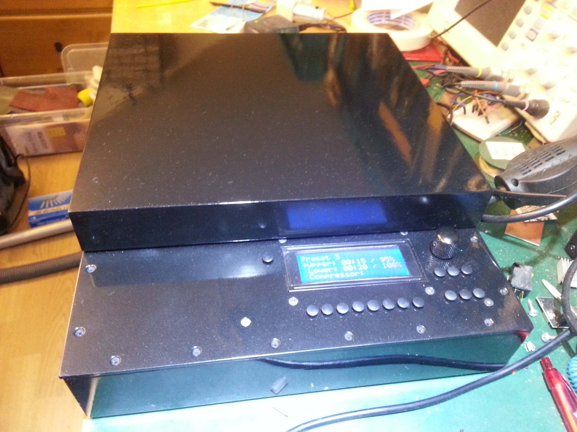
- User feedback through a 20×4 character backlit LCD display with adjustable backlight and contrast plus a piezo beeper.
- Tracking of runtime. The total on time is tracked. And the runtime of the two light panels and the vacuum pump are tracked with two values each. The absolute time running and the time scaled by the power/speed they where running at.
- Wear balancing of the EEPROM. Some values in the EEPROM is updated fairly often. Like the currently selected preset. And the runtime counters. So each of those values have multiple locations allocated for them in the EEPROM and new values are written to a new location each time until all slots for the value has been used. Then it will start over. This ensures that the guaranteed 100.000 erase/write cycles will last as long as possible.
Light panels
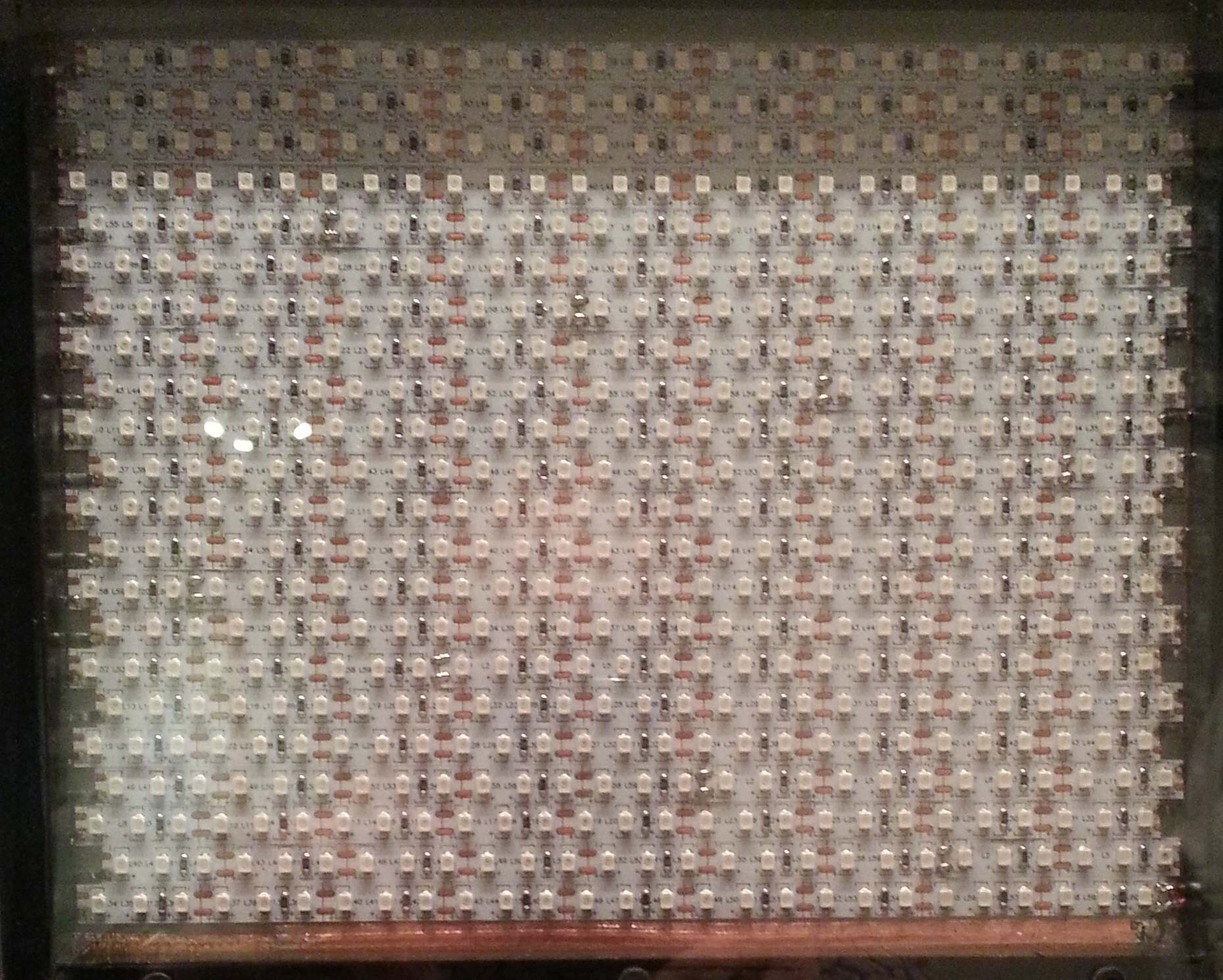
LED panel. As far as I could tell, this layout would give the most uniform light distribution.
I started by cutting two pieces of 0.7mm sheet steel and cover one side of each with a thin adhesive plastic film. The plastic film ensured that the power traces under the LED strips could not contact the steel. I then cut each LED roll into 22 pieces having 27 LEDs each. Then I glued 22 strips to the plastic film covering each steel plate. The strips was placed as tight as possible and with every second strip offset half a LED spacing to make the pattern as tight and uniform as possible.
Along each end of the strips I added two strips of 5mm copper tape for power distribution. I then added a small piece of copper tape from each negative pole on the LED strips to one of the copper tapes, and then from each positive pole to the other copper tape. Now all the LED strips was connected in parallel and could easily be powered with a pair of wires.
After finishing the first panel I run a few exposure tests to make sure the 395nm light was at all able to activate the dry-film photo resist that I was planning to use. And the test results was very positive. My old method of exposing was a 36W fluorescent light nail curing machine. And with that one I had settled on 2 minutes exposure time. When calibrating the LED panel it turned out that the optimal exposure time was 6 seconds. So I guess that the higher efficiency of LEDs vs tubes was about 24 times more important than the wavelength difference between the two. At least for the dry-film photo resist.
When testing it with the liquid UV hardened solder resist that I use the results was rather disappointing at first. It seemed to partly work but the surface would be matte and sticky. So I reckoned I would have to stick with the nail curing machine for that part. But then I happened to read an article about how oxygen could inhibit the photoinitiated polymerization of resins. So I did a new test where I covered the wet solder resist with a sheet of cellophane plastic. This is how I usually achieve a smooth and dust free surface anyway, but I had not bothered during the initial tests. With the resin protected from the atmosphere it cured perfectly. Not nearly as quick as the solder resist, but at about the same time it took the 36W fluorescent lamp to do it. Which is about 2 minutes. So I was happy.
The enclosure
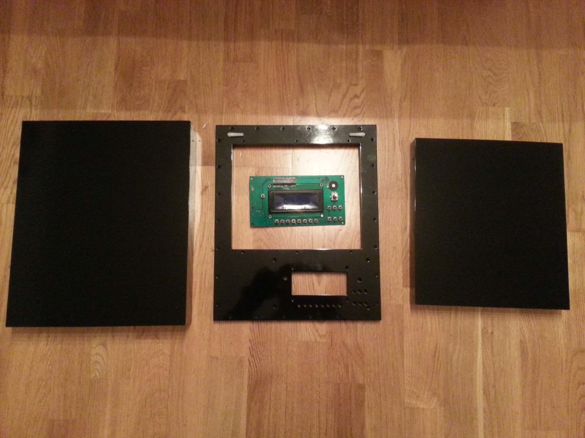
After verifying that the light panels would do the job, it was time to build an enclosure for the them. I built the enclosure from 15mm thick wood boards for the sides and 3mm hardened MDF plates for the covers. I built two boxes. One slightly larger than the other. The larger box is used as a base and have a 3mm plate glued to the bottom and another 3mm plate screwed to the top. The top plate have cutouts for the lower led panel, the LCD display and the user interface buttons.
The enclosure base

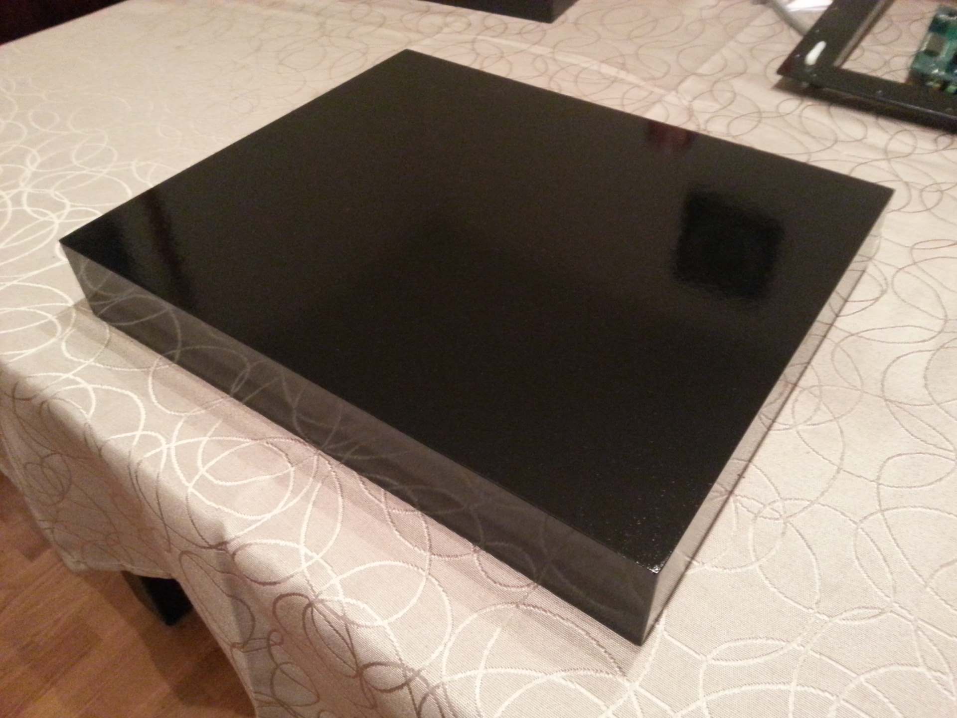
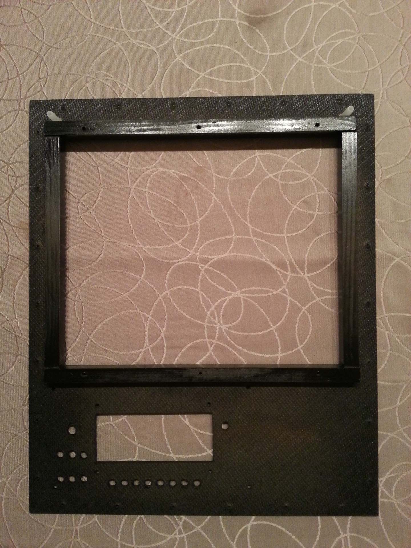
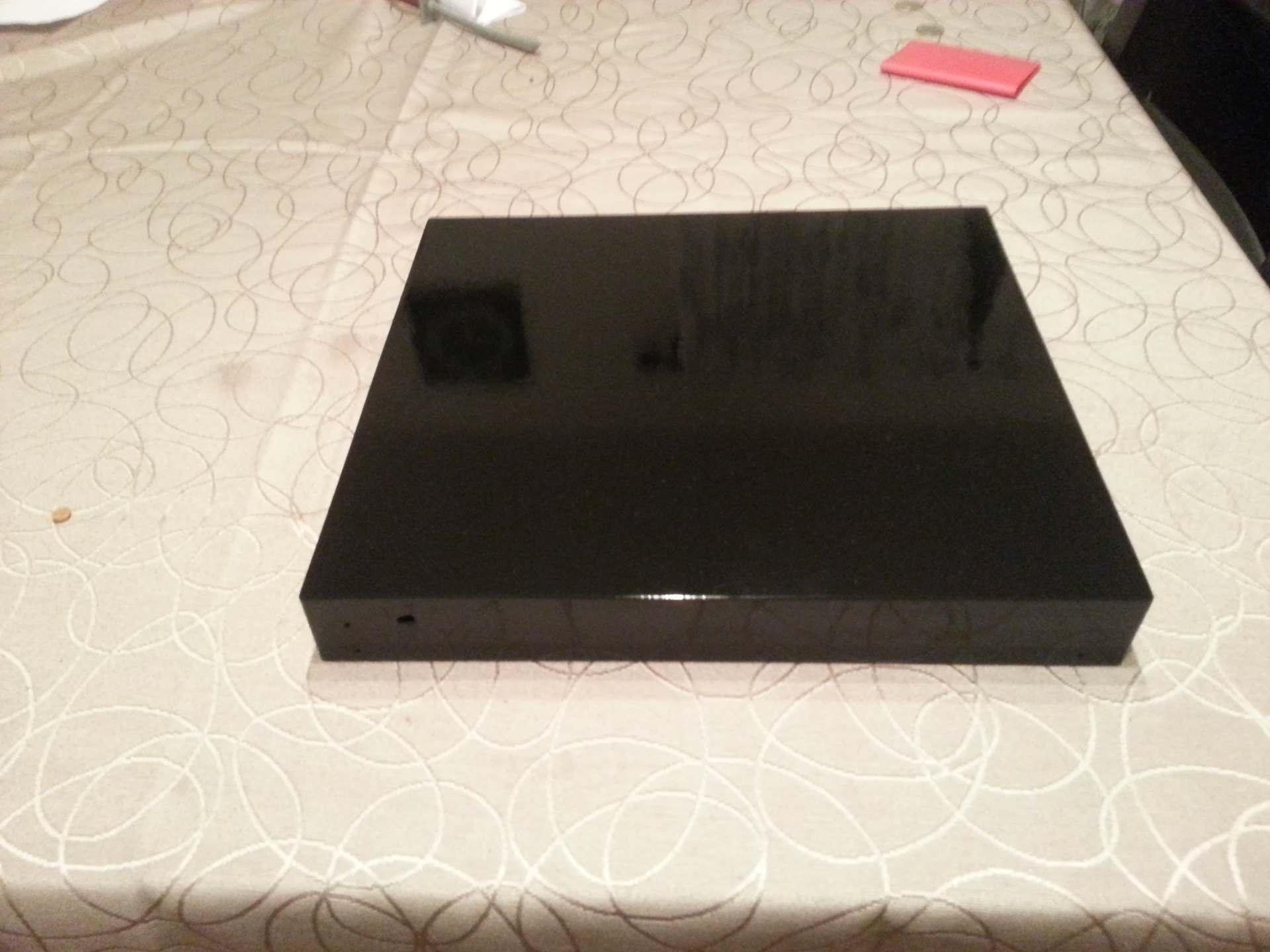
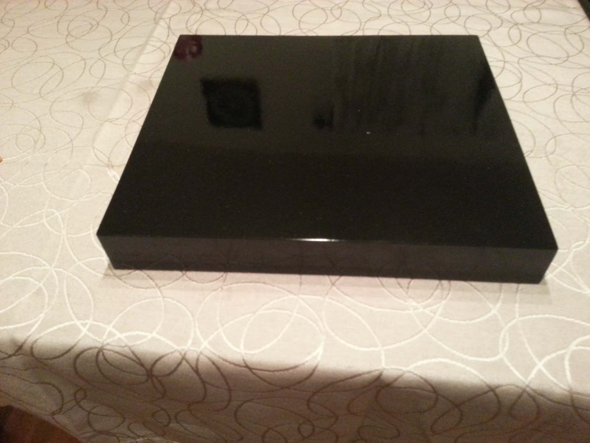
Left side is the inside of the base, right side is the outside. The base has been primed on both sides and painted on the outside.
The base is a simple 34.5 x 29cm box with cutouts for a power connector and a programming connector at the back. The bottom is permanently covered by a 3mm plate that is glued in place. The side walls are 5cm tall. I first cut the 4 side walls with 45° miter corners and glued them together. Then I make a slightly over-sized bottom plate and glued it in place. When the glue had set I sanded down the excess from the bottom plate.
I did pretty much the same with the base cover. I made a slightly over-sized plate that I screwed onto the base with 26 small screws (pre-drilling each hole using a 1mm bit in a drill-stand). I then sanded it down to a perfect fit.
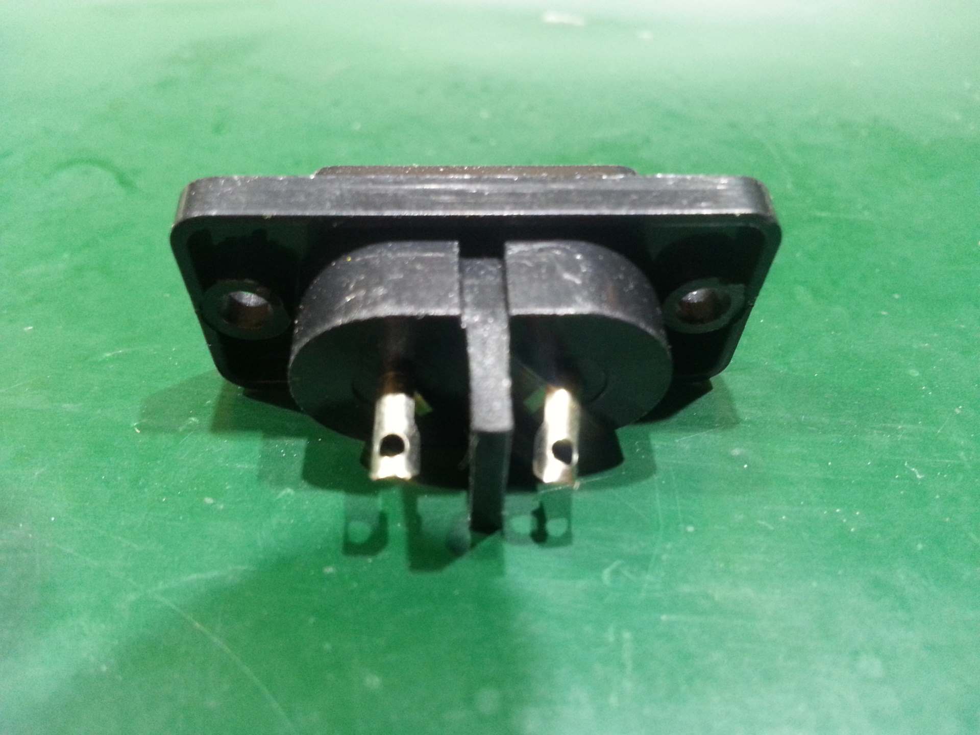
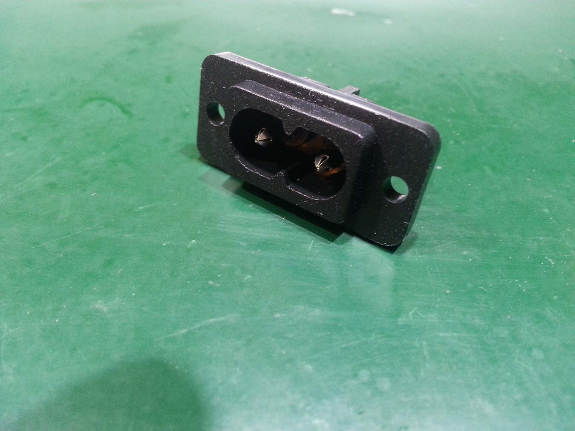
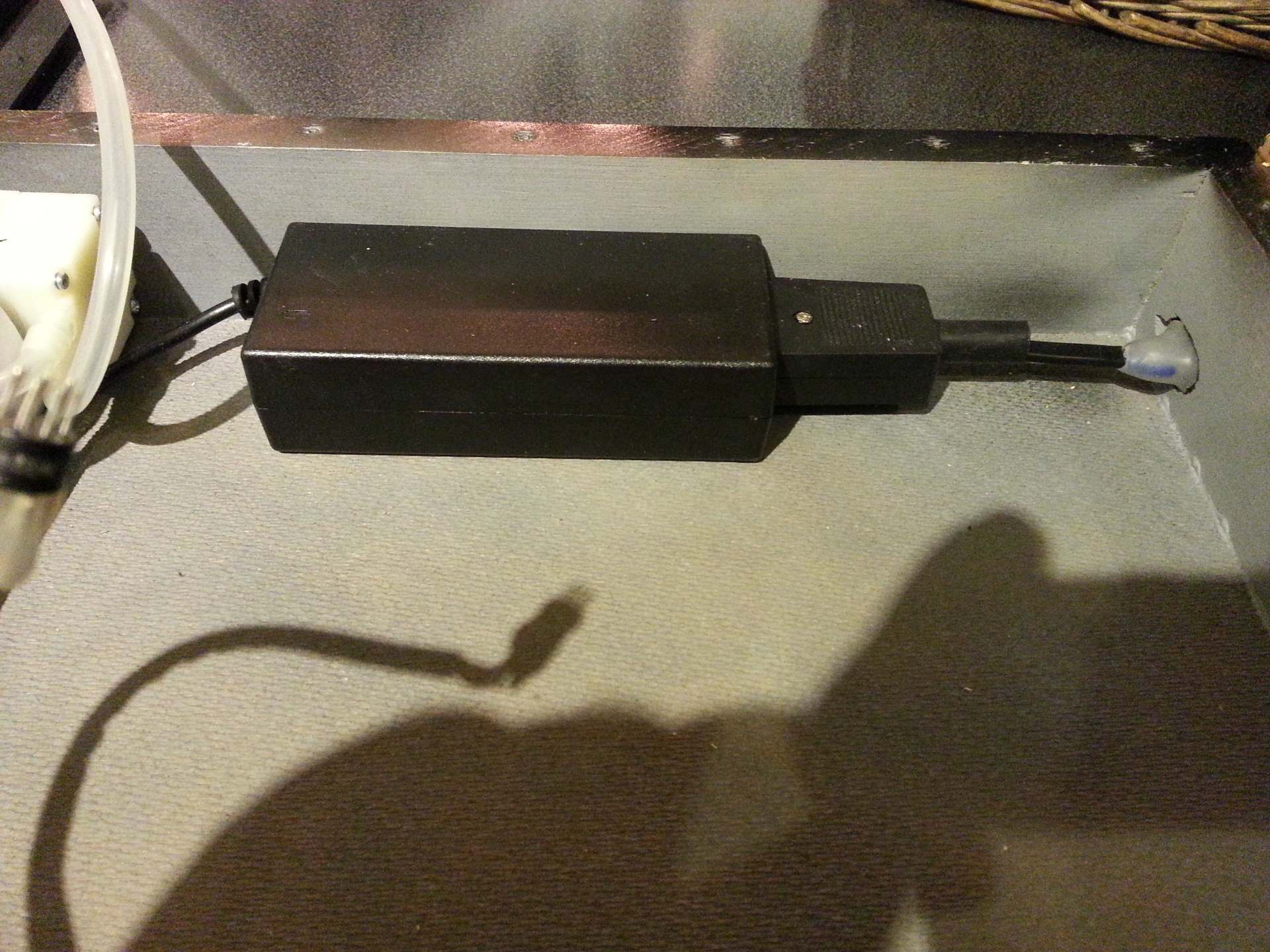
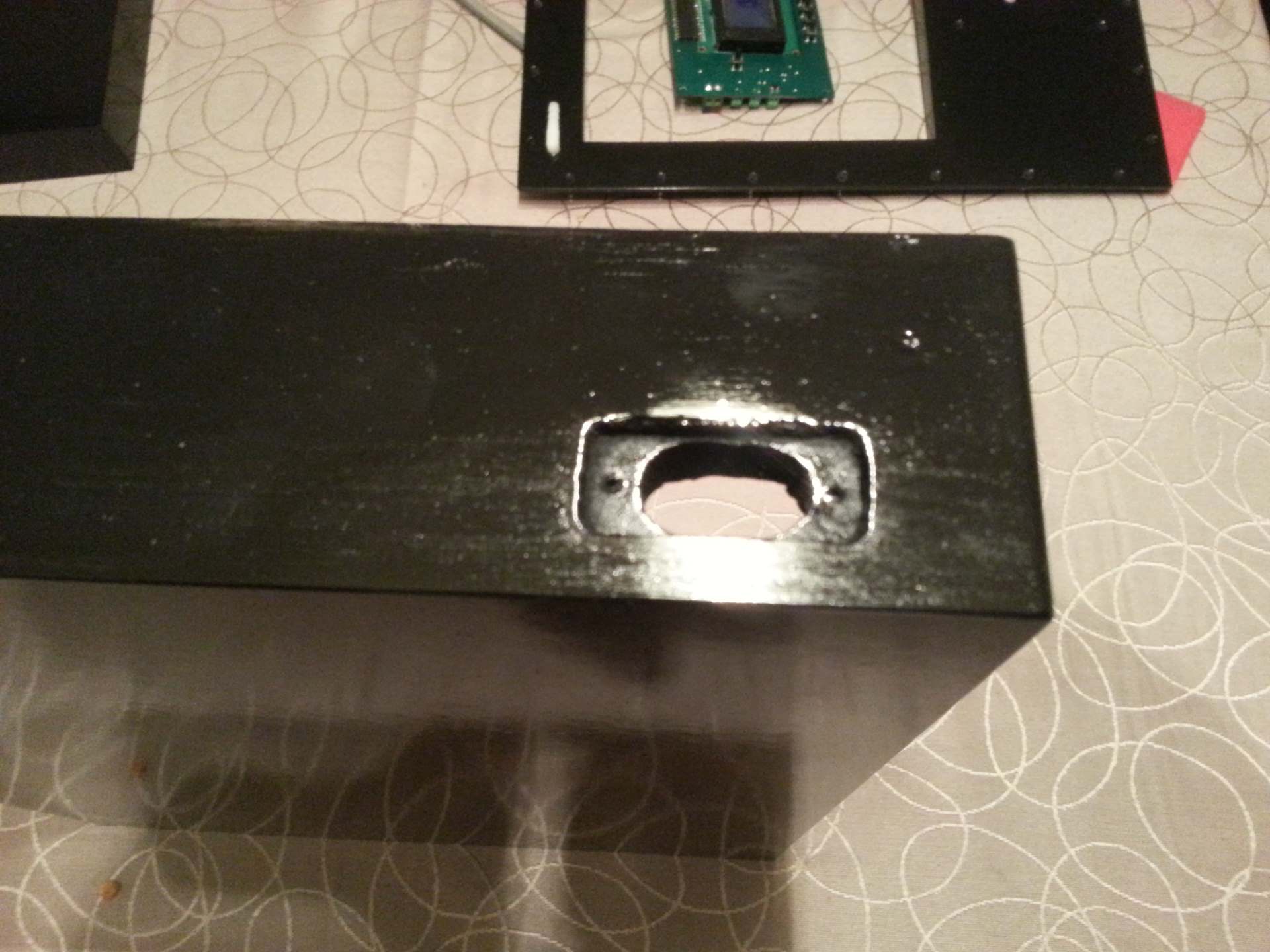 I used a dremel with a palm-router tool to machine out the slot for the power connection. First I routed the 12x20mm oval hole for the socket and then counter-sunk the square part of the connector. This server two purposes. First to prevent the connector from extending outside the box. Second to make the actual connectors extend inside the box. The latter turned out to not be very important though, as it made most sense to solder wires to the connector before inserting it into the box any way. After soldering the wires I fully enclosed them in hot-glue to make sure they could not come in contact with the wood or be accessed in any way.
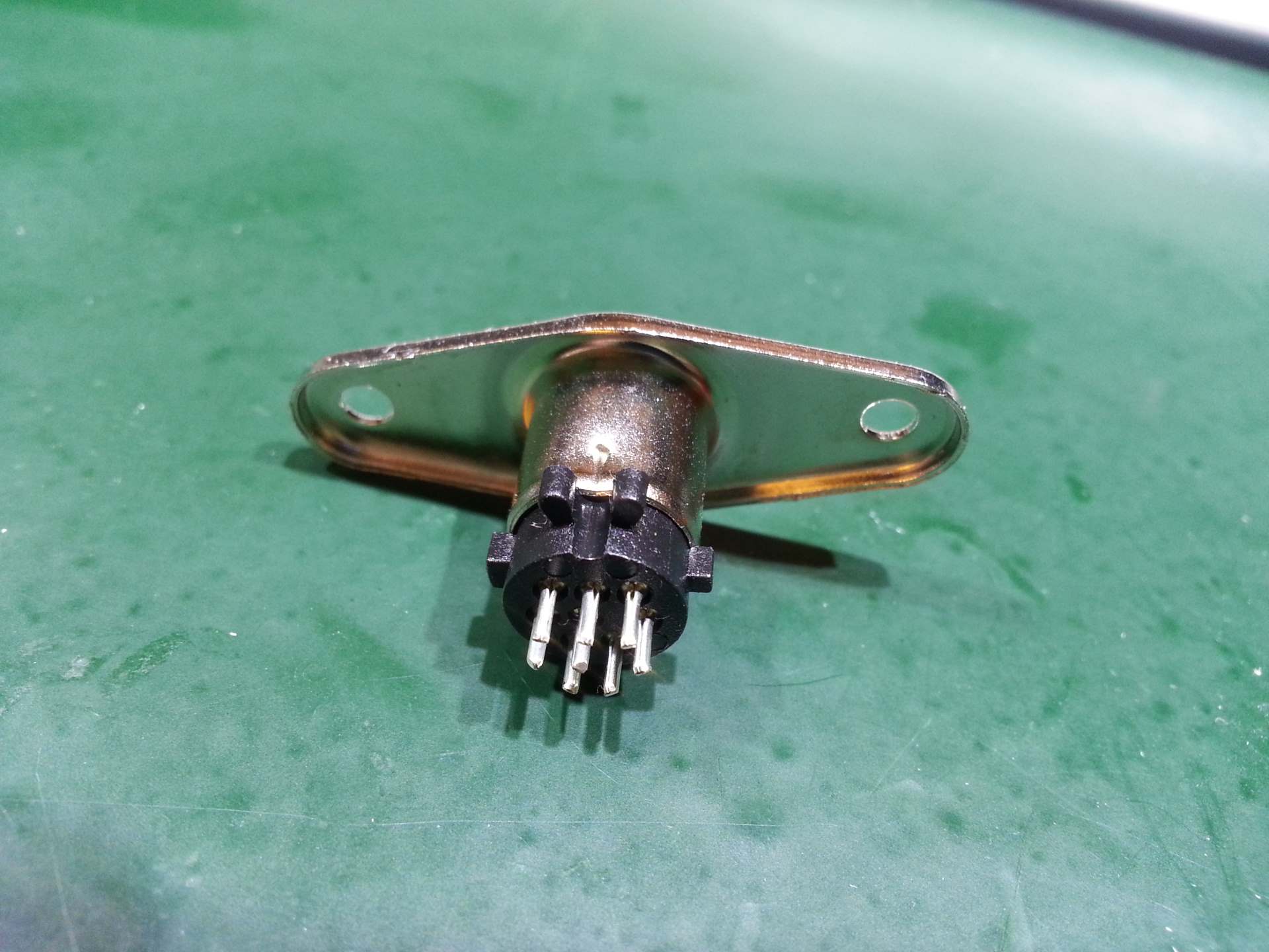
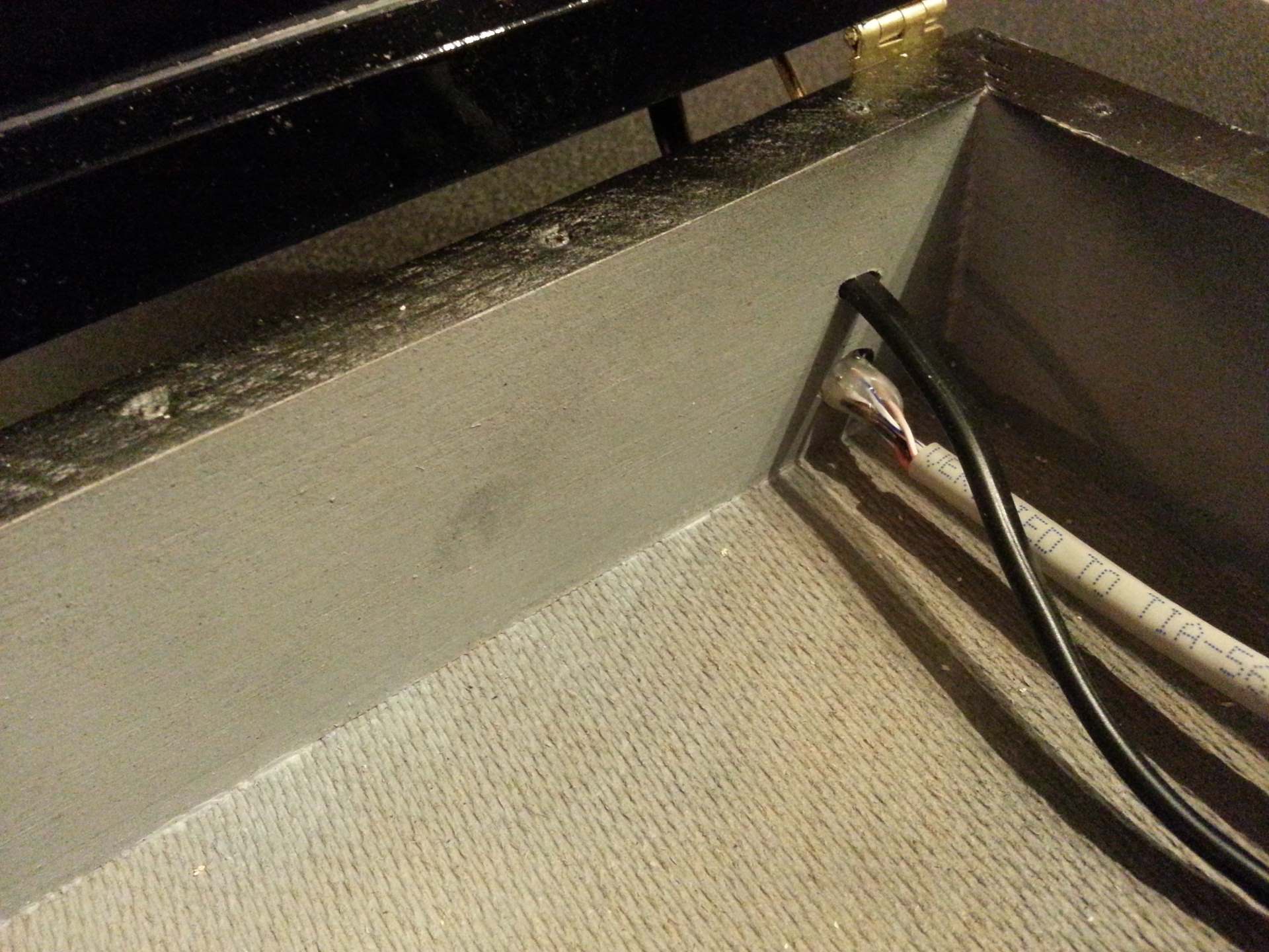
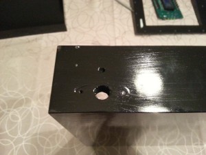 Since this is supposed to be a working prototype I needed a convenient way to program it. Pulling the lid of each time does not count as convenient. Especially not when the lid is held in place by 26 tiny screws. So I extended the controller PCB ISP+ connector to the back of the box and exposed it through an 8-pin mini-DIN connector. More on the choice of connector later. The small hole above the connector cutout is for the power cable going to the LED panel in the lid.
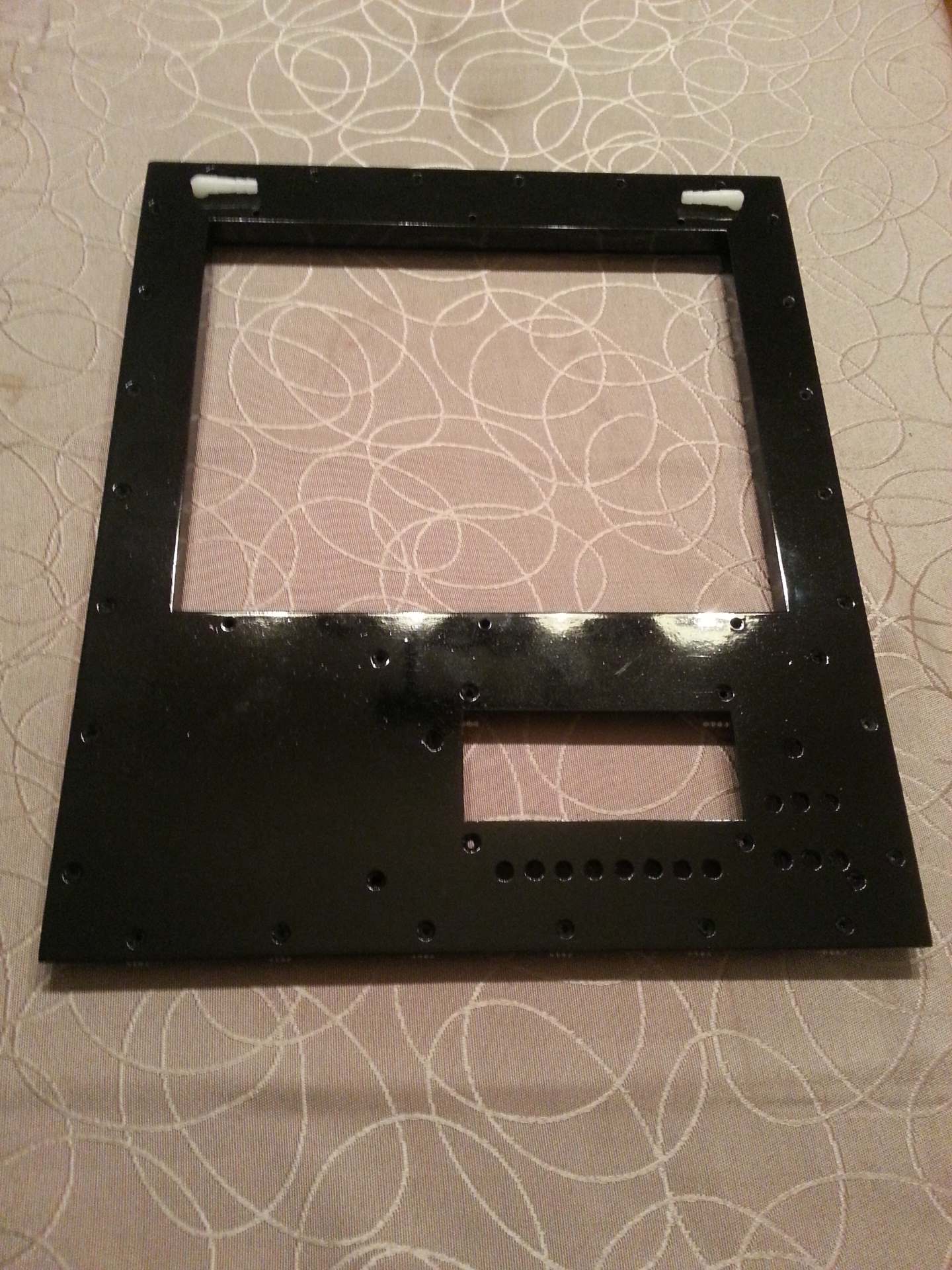
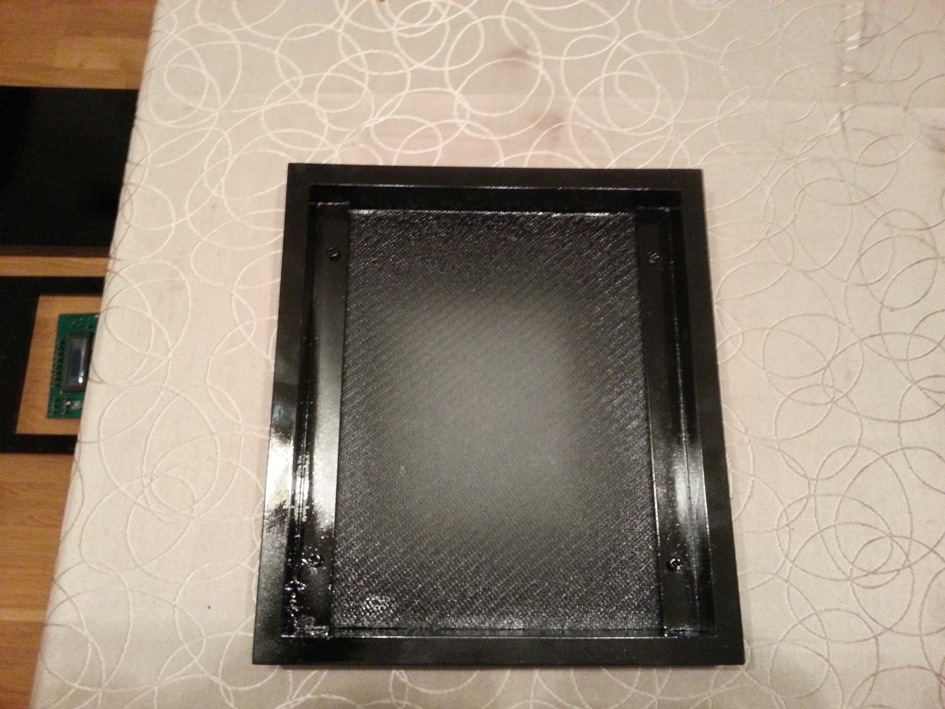
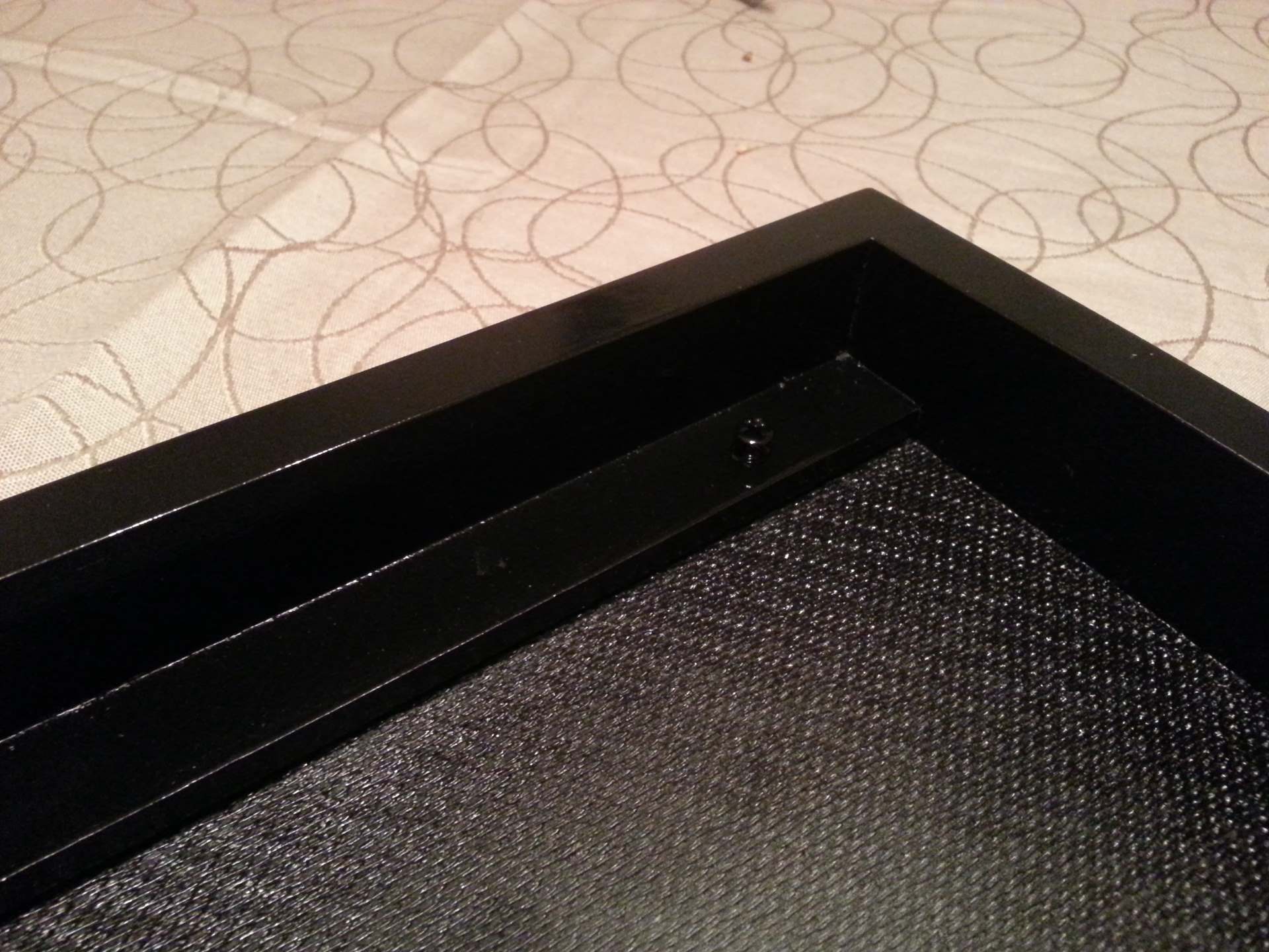
Like mentioned above I sized the base cover by screwing it onto the base and sand it down. After that I made a frame around the opening on the back-side using 12x12mm wood strips. First I shaved off ~3mm from one each of each of the vertical strips to make space for the power rails and connecting wires. Then I glued the 4 strips onto the back of the cover to make a frame for the lower LED panel. When the glue had set I used a jigsaw to cut out a hole. Cutting as close to the frame as I dared. Then I sanded inside the hole to make the plate completely flush with the frame. Then I made a plexiglass window that was slightly larger than the hole. I then temporarily placed one of the LED panels towards the frame at the back and the plexiglass window towards the front and drilled 6 3mm holes. I countersunk the holes in the plastic to make the screws completely flush with the window.
In the first iteration I did not sink them deep enough and that turned out to be a bigger problem than I had anticipated. The extended screws tended to tear up the plastic bags I use for vacuum lamination of the artwork and PCB. So I dug out the drill again and made sure the screws was completely flush.The total distance from the LED’s to the surface of the plexiglass is 12+3+4-2 = 17mm. That is 12mm for the frame + 3mm for the lid + 4mm for the plexiglass and -2mm for the height of the LED’s them self. This distance is slightly arbitrary but not entirely. I first did the following calculations to find the minimum distance:The max spacing between the LEDs are 8.3mm. And the viewing angle is 120°. If the LED light circles was made to have a radius of 4.15mm they would touch each other and there would be no overlap. But there would be open spots between them. To calculate the radius needed to fully cover the area a little Pythagoras is needed:Min radius = sqr(4.15*4.15 * 2) = 5.87mmTo make that radius with a 120° viewing angle the distance will be:
Min distance = 5.87 / tan(30) = 10.17mm
This is valuable information to have. We now know that if we make the distance smaller than 10.17mm we are guaranteed to fail. But since the intensity of the light will be much higher in the center of the circle than towards the edges using exactly 10.17mm would probably give a fairly uneven coverage. And this is where things started to become more arbitrary. I don’t really know what to multiply 10.17mm with to get the distance that provide the best balance between faded areas caused by to little overlap and hotspots caused by to much overlap. By doing some test exposures I came to the conclusion that 19mm spacing between the metal plate holding the LEDs and the surface of the PCB gave a very uniform radiation. So that is the number I picked.
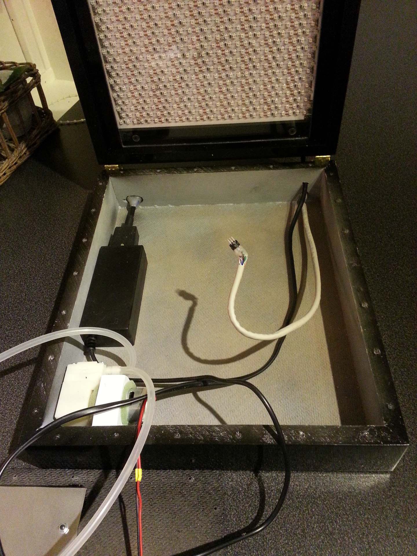
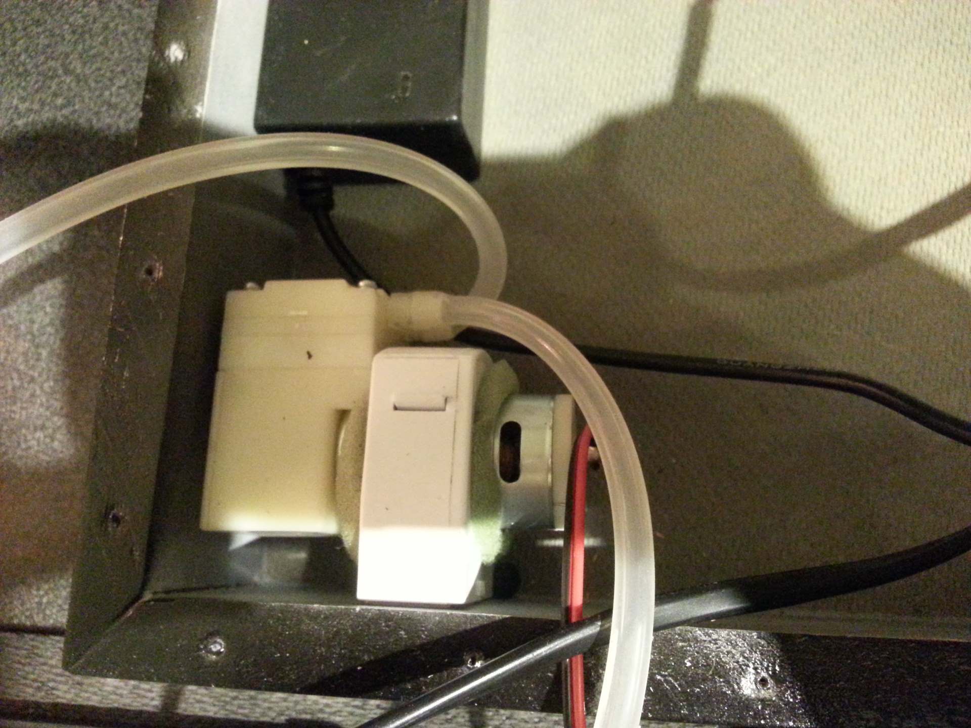
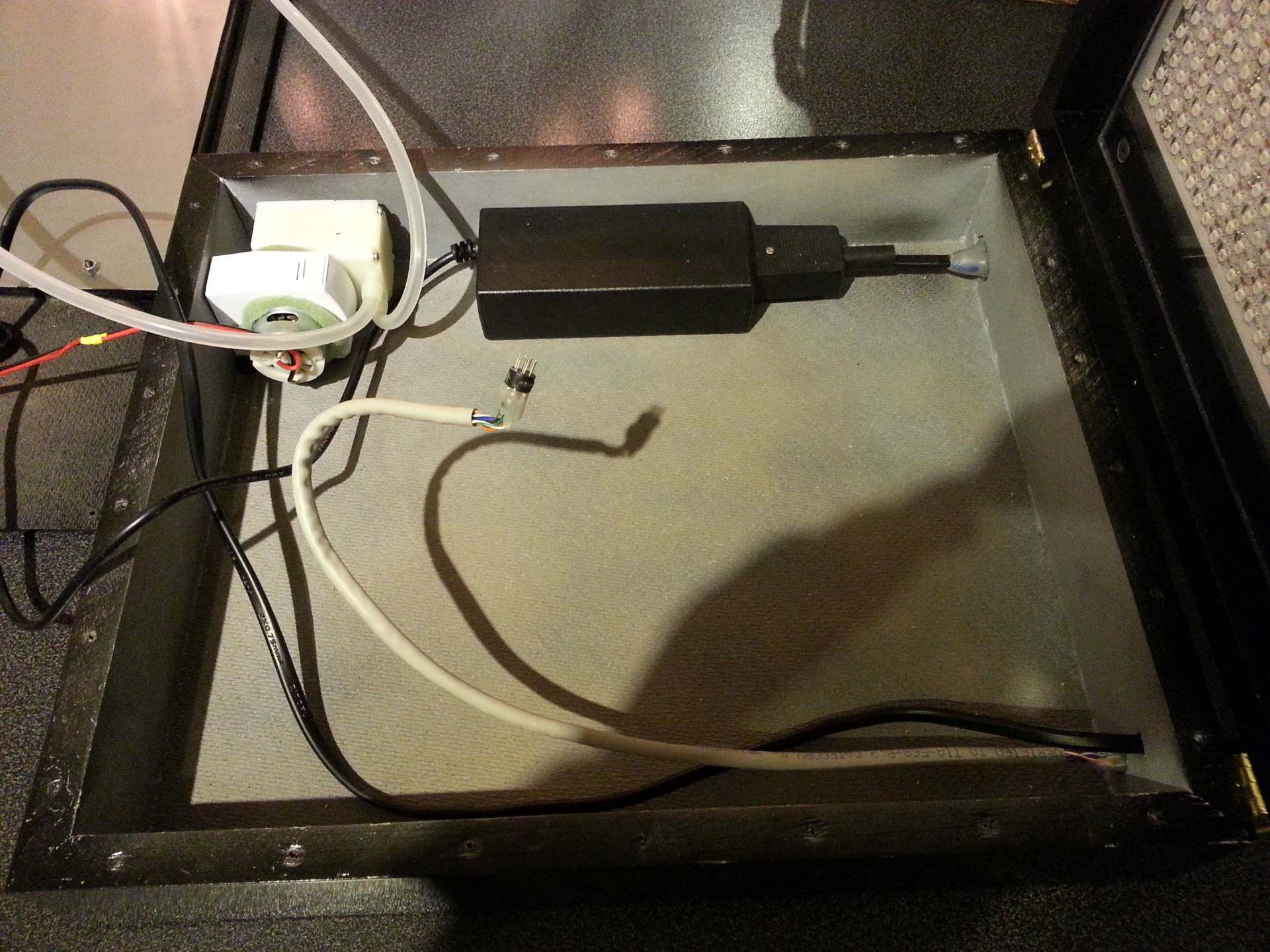
The two white nipples you see at the top is the inlet and outlet for the built-in vacuum pump. They are both positioned inside the lid to make it easy to place a vacuum bag around the PCB and artwork and then connect it to the pump. Any air that leaks into the bag will be pumped out the outlet so even if the seal between the lid and the base turned out to be perfectly air tight the system would still work. That seal is very far from air tight tough, but I believe the design still makes sense.
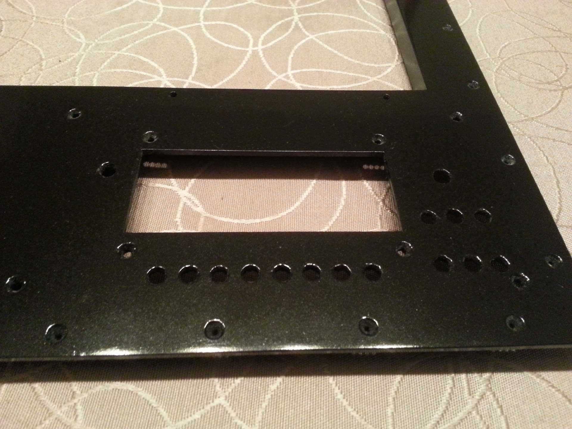
Now I had to make the cutouts for the display and user interface switches. I have made several CAD drawings for this project. A full 3D-drawing for the enclosure in Sketchup Make, a PCB layout for the controller card in Diptrace, and a 2D vector drawing for the front-panel artwork in Inkscape. The relative positioning of display and switches is of course defined by the PCB layout. And in the vector graphics for the front panel I have a guide layer where the outline for the display and the position of each switch and knob as well as the mounting holes are marked. I printed out this layer 1:1 and taped it on top of the front panel. Then I used a center punch to mark all holes that had to be drilled and each corner of the cutout for the display. Then I drew 4 lines between the LCD corner markers and started drilling and cutting.

The enclosure lid
The lid is built pretty much the same way as the base. First I built a frame using 15mm wood boards and then glued 3mm hardened MDF plates to both the top and the bottom. At the bottom I then cut out a big hole with the jigsaw close to the edges. Then I sanded the inside to make the MDF cover only the edges of the frame. This ensured a smooth surface where the lid would land on the base.
Then I cut two 6x21mm wood strips to fit exactly inside the box. I drilled two holes in each strip and mounted a blind nut in each hole. Then I glued one strip toward each long edge of the box with the nut head facing the top cover. In the images you can see there is a screw threaded into each of the nuts to make sure no paint would clog up the threads when I spray painted the box.
This strips are what the upper LED panel and plexiglass window attaches to. The top of the strips are mounted 25.7mm below the edge of the box. This will give 21mm clearing between the top of the metal plate the LEDs are mounted to and the top of the plexiglass window in the base where the PCB will be placed. This again will give a distance between the metal plate and the top of the PCB of 19mm if the combined height of the PCB, artwork, and vacuum bag is 2mm. So the same as the distance from the lower LED plate and the bottom of the PCB. It is 25.7mm because the 19mm spacing + the 0.7mm metal plate + the 4mm lower plexiglass + the 2mm PCB/artwork adds up to 25.7mm.
The LED panel is placed directly on top of the mounting strips, then a frame made of 4 6x21mm wood strips are placed on top of the LED panel. The plexiglass window then goes into the frame. The frame is made by gluing the short edges on top of the long edges so it has a total height of 12mm and the top of the plexiglass rest agains the long strips while the ends of the glass touches the short strips. Then 4 screws goes through the plexiglass, the long edges of the frame, the metal plate and finally into the blind nuts placed in the mounting strips.
The controller PCB
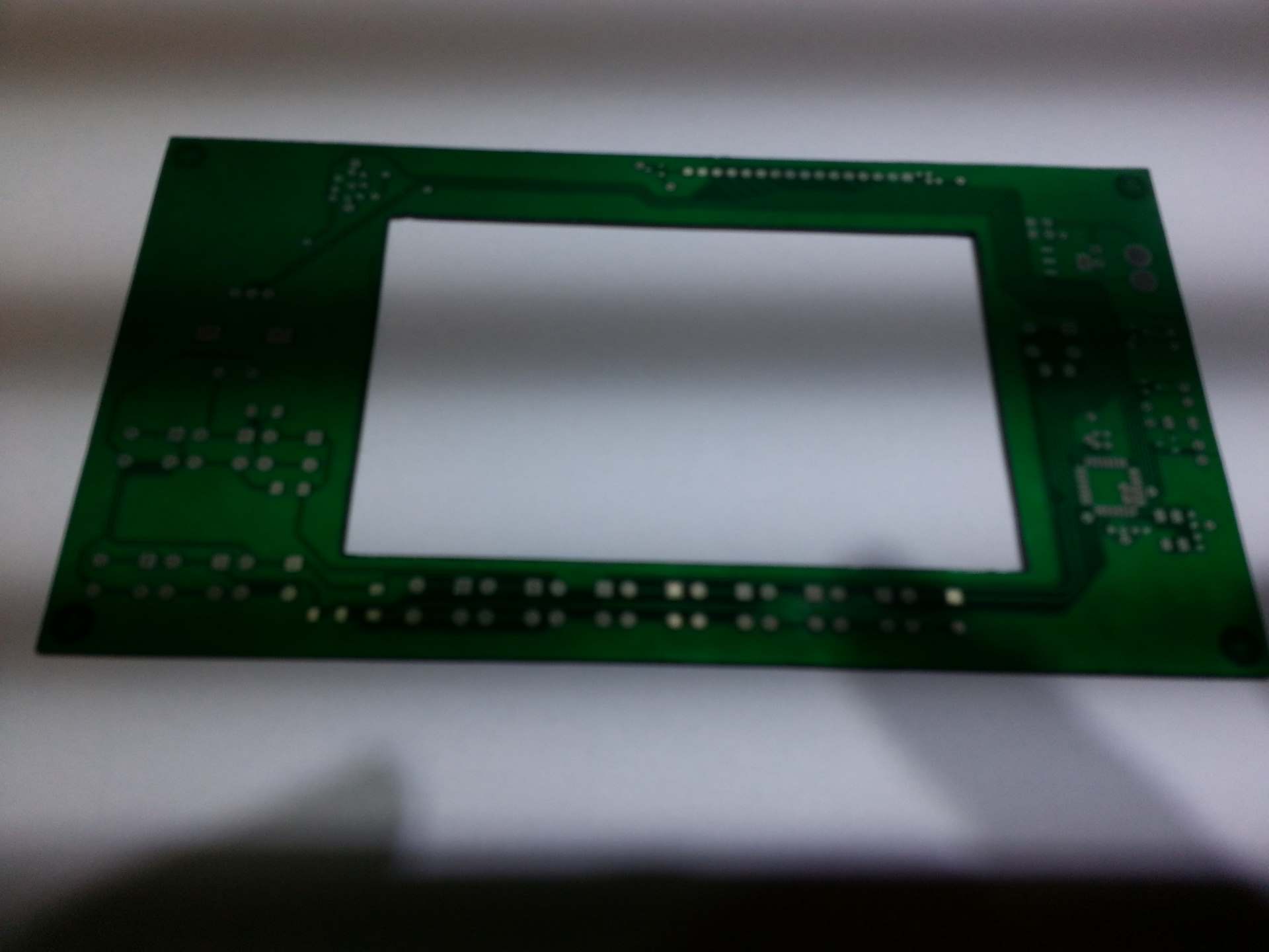
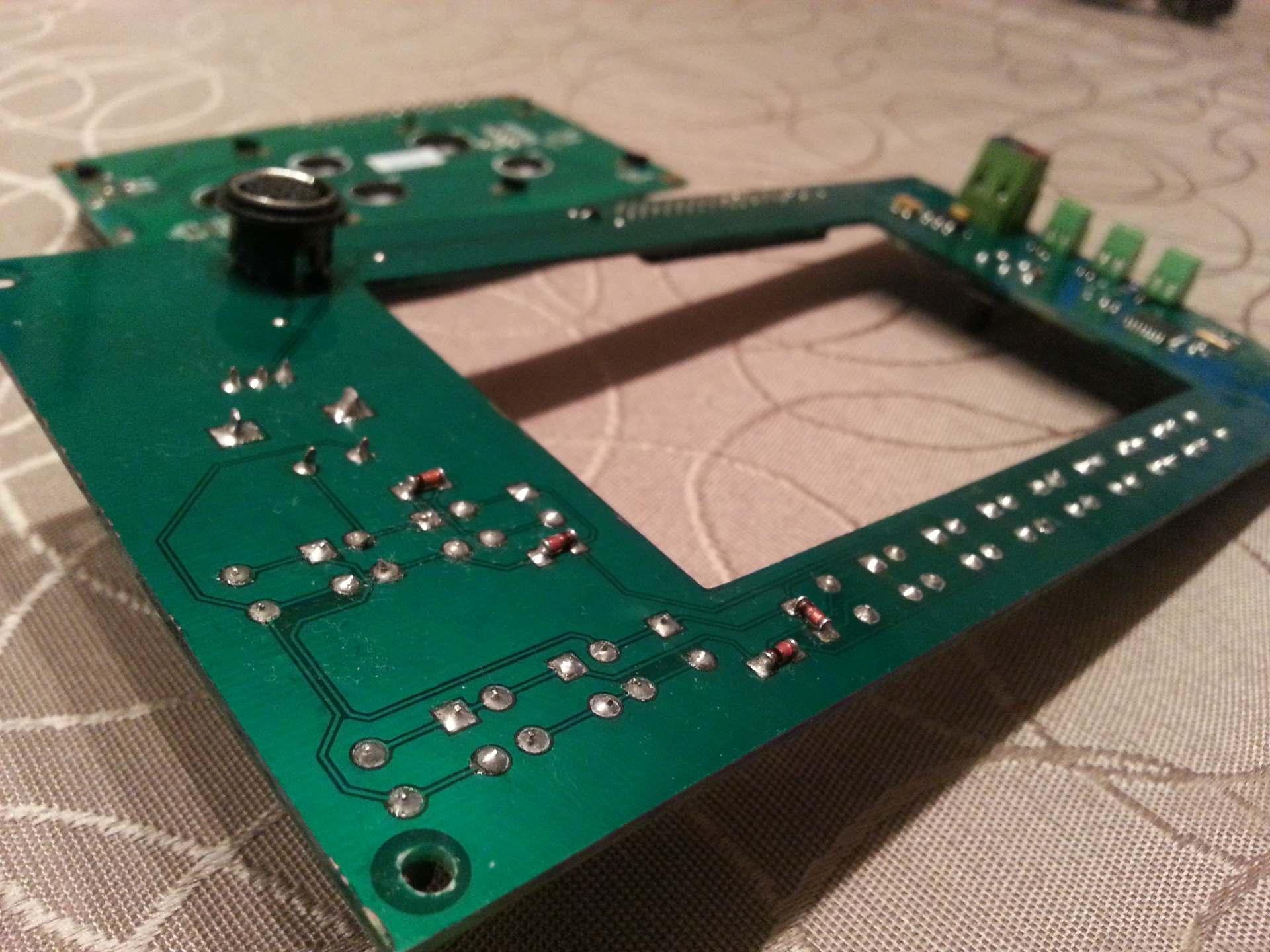
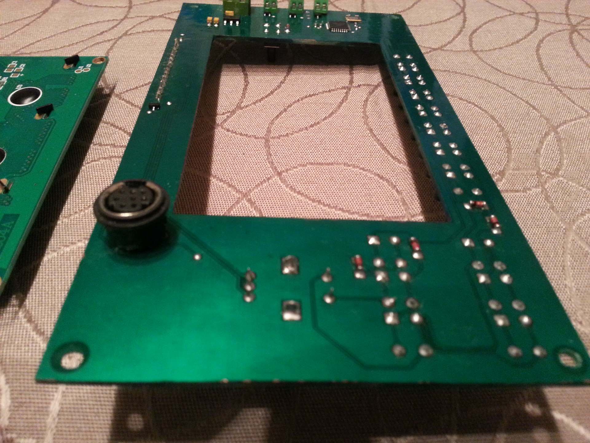
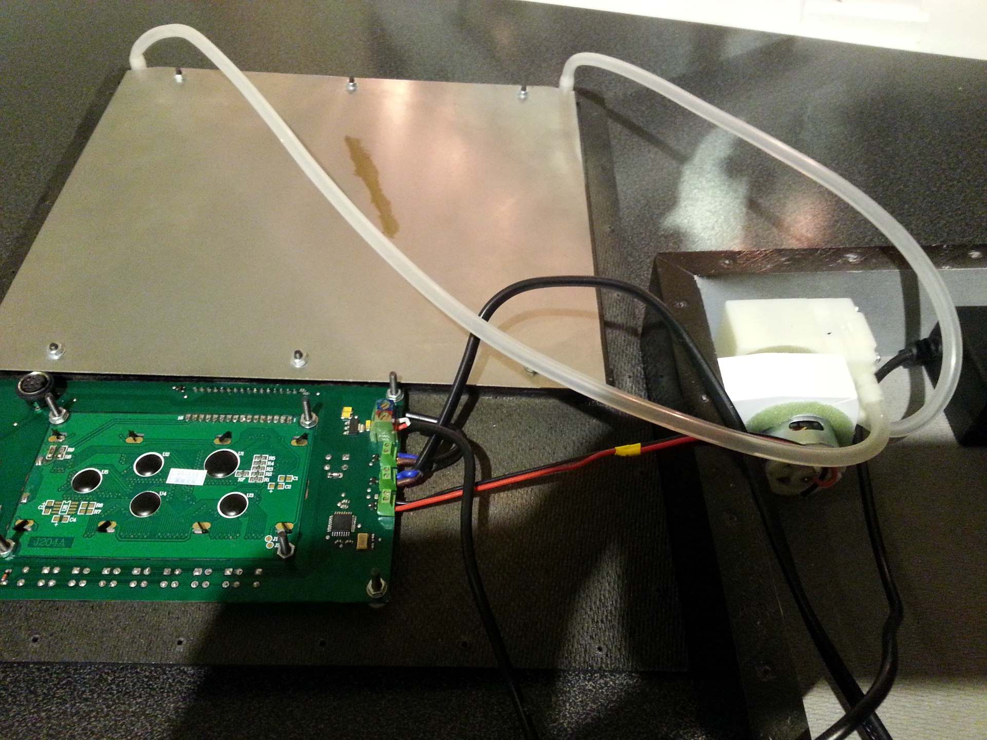
The controller PCB is made by the unit itself. After doing the initial tests of the light panels and figuring out the optimal distance between the LEDs and the PCB I used one of the light panels and one of the plexiglass windows to make the PCB. I of course had to time it manually and manually flip it over to do both sides, but it worked very well. The controller PCB turned out pretty nice.
Mechanical properties
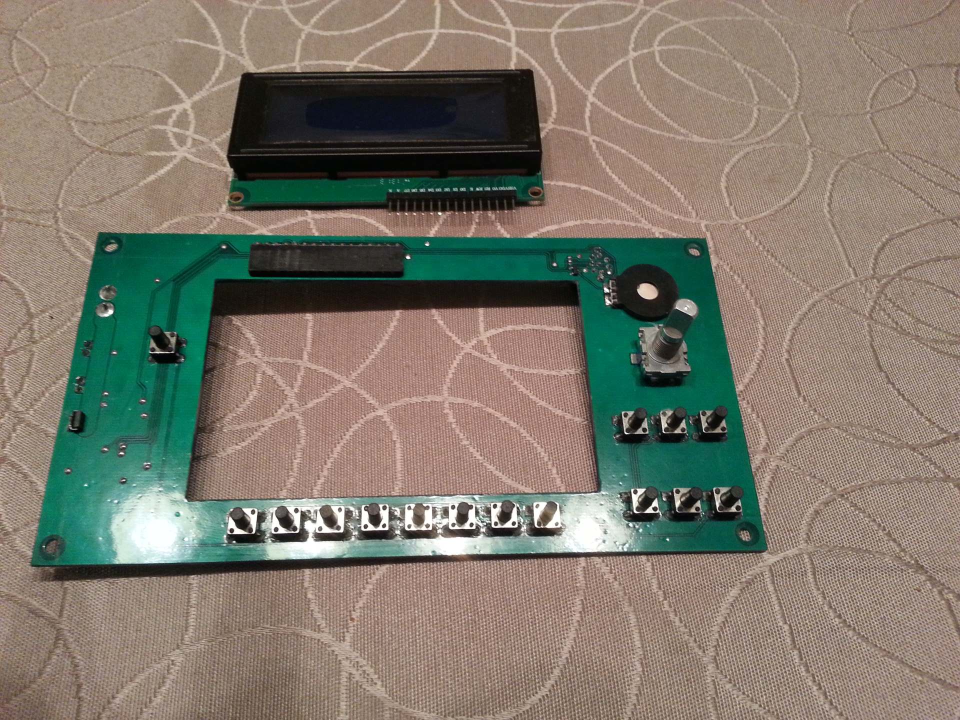
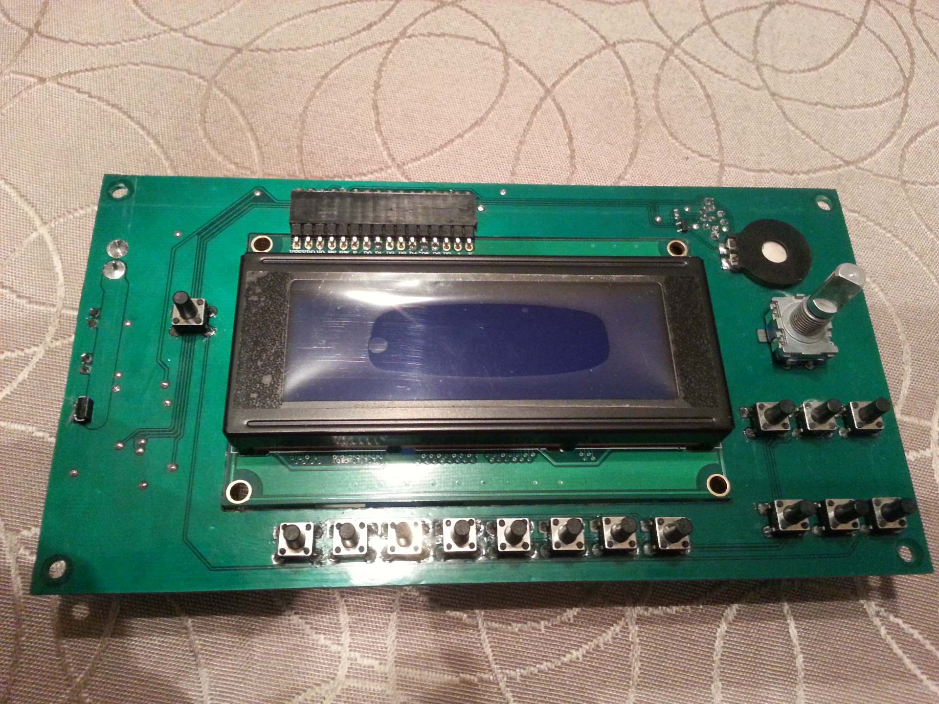
The PCB holds the following “interface” components:
- 15 micro switches for the keyboard.
- A rotary encoder with push button.
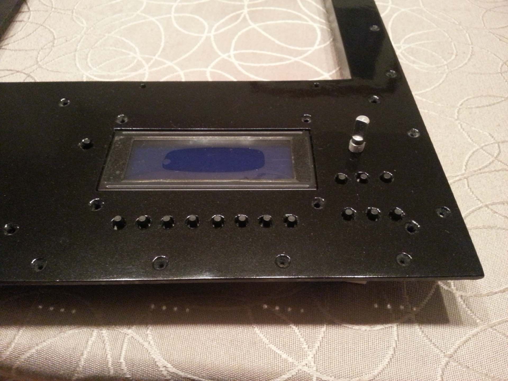
- A 20×4 character LCD display with backlight.
- A (passive) piezo beeper.
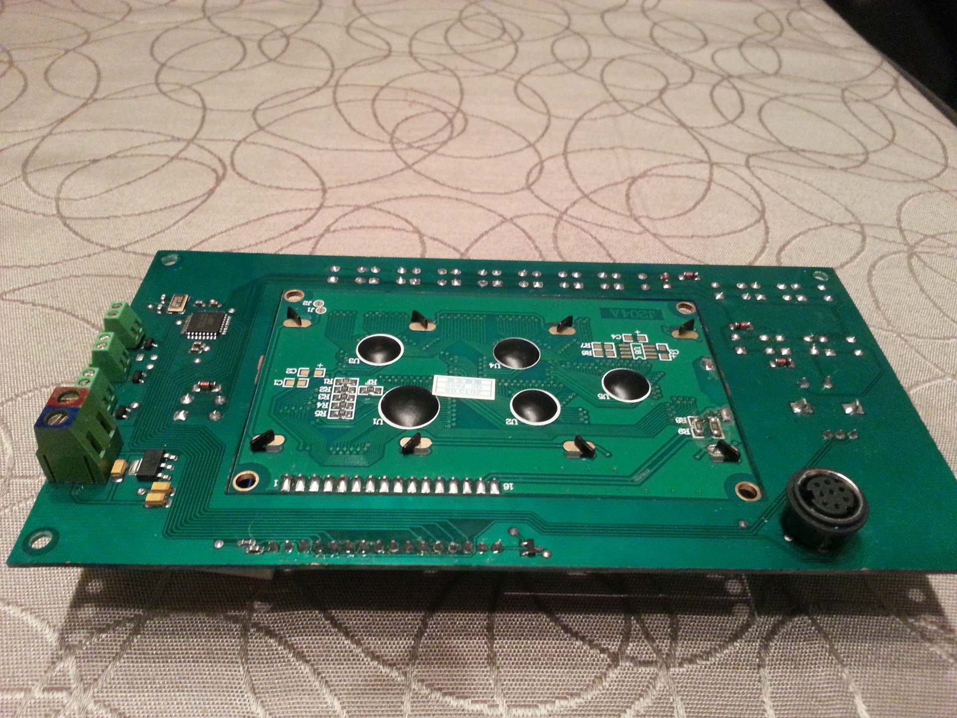
- A large wire terminal for power in.
- 3 smaller wire terminals for power out to the two light panels and the vacuum pump.
- An 8-pin mini DIN female connector for programming (ISP port).
The mechanical side of the controller PCB turned out to be much more tricky than the electrical side. The main reason being that all the buttons, the rotary encoder knob and the display all had to be at the same level. And the buttons / knob would be distributed all around the display. My first plan was to make multiple PCBs. One main PCB with the microcontroller and one for the keyboard (or maybe more to make it easy to place the different buttons around the display) and maybe one for the rotary encoder. Although the rotary controller and the LCD module could have wires directly soldered to them.
This would make it easy to adjust the individual height of each type of component that had to extend through the front panel. But it would be much more messy than the solution I ended up with as there would be ribbon cables going everywhere and I would have to make multiple PCBs.
Due to the complexity and labor intensity of the multiple PCB solution I started looking closer into the height of each user interface component. The first problem was the micro switches vs the rotary encoder. The body of the micro switch I wanted to use is 3.8mm tall. The rotary encoder is 6.7mm. But you can get those switches with a long stem that makes the total height 9.7mm (when pushed). And with the front panel being 3mm thick I then got 5.7mm space between the PCB and the bottom of the front panel when the stem extended 1mm above the front panel. That is only 1mm less than the height of the rotary encoder body. And that could be solved by putting a 1mm spacer below the switch while soldering. With 4 through hole legs it would be plenty stable even without the actual body of the switch resting against the PCB.
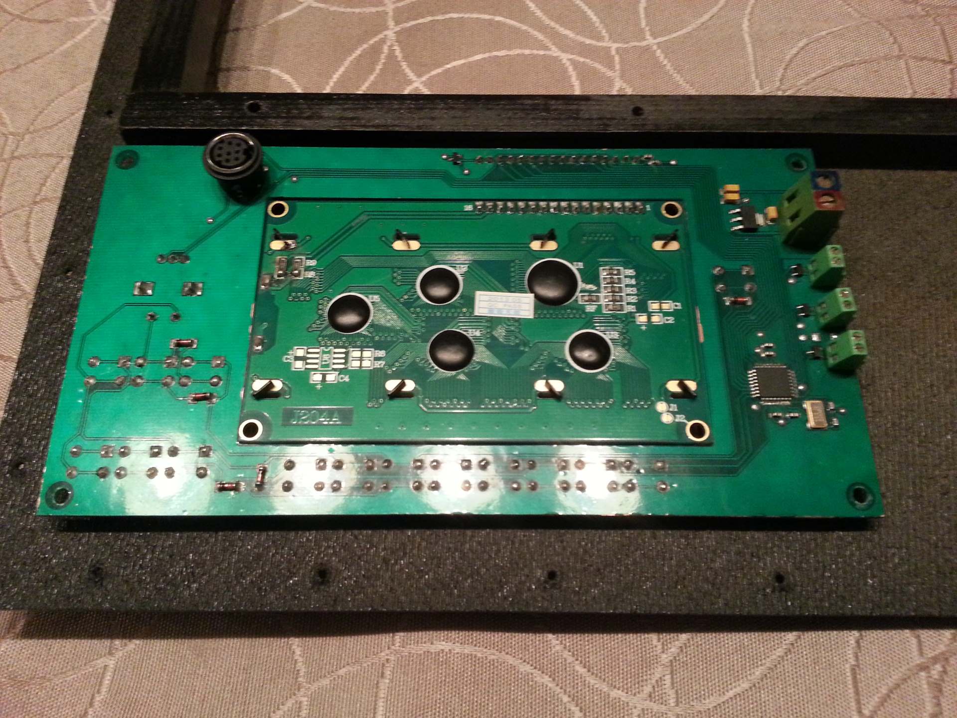
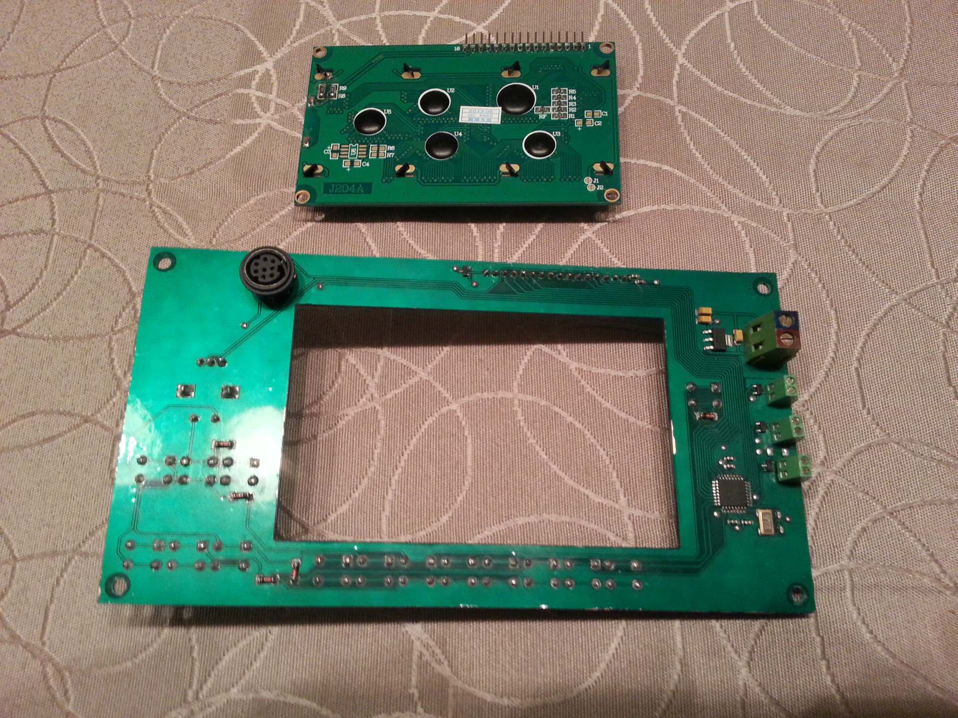
Then the only problem was the display. My first idea was to place the LCD module PCB on top of my PCB and make the connection by threading bare copper wire stubs through both PCBs and solder it to both. I could either put the display module on top and only make small holes in my PCB for the metal tabs that fix the LCD to the PCB of the display module. Or I could put the display module at the bottom and make a bigger hole that the whole screen would fit through. The problem however is that the display part on top of the controller PCB of the LCD module is 9.6mm tall. And since the distance between the controller PCB and the front panel is 6.7mm (dictated by the rotary encoder) and the front panel is 3mm thick neither of those solutions would be very good. Putting the LCD below the PCB would make the display be 1.7mm to low. And putting it on top would make it 1.5mm to high. And I really wanted it to be flush.
By now it was clear that the only way to achieve that was to have the two PCBs at approximately the same height. So a bigger hole was needed. One that would allow the whole LCD PCB to fit. This of course made it impossible to connect the two PCBs by threading wires between them. So I ordered some angled connectors that made it easy to connect the two PCBs. This solution was great. Now it was super easy to make the display flush with the front panel and have all the control components extend the right amount. The LCD module and the controller PCB is individually fixed to the front panel with 4 screws each. And since there is a little flex in the connection between the two I could now shim each of them individually to make the alignment perfect. And there is no loose signal wires in the box. Only the power cables to and from the PCB.
I used plastic washers to shim it. Mainly because at this point I realized that the PCB had a slight design flaw. The bottom side is mostly covered with a ground plane, and the top side is mostly covered with a power plane. And the clearing around the mounting holes was not big enough for the washer to fully clear the copper. So if I had used metal washers and they would have punctured the solder mask on both sides I would have a nasty short. With plastic washers against the power plane and the screw head against the ground plane the worst thing that can happen is that the screw becomes grounded.
Functionality and features
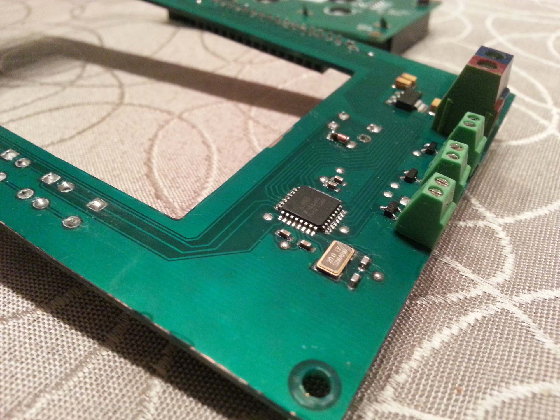
The controller PCB have 4 main duties. Take user input through the keyboard an knob. Communicate back to the user through the LCD display and the piezo beeper. Control the power to the light panels. And control the power to the vacuum pump. In addition it need to regulate the 12V used to power the light panels and compressor down to 5V to make the LCD display and MCU happy. And it need a functioning in-system-programming (ISP) connection.
The MCU I picked for this project was the ATmega88. It is very cheap and I thought I would be able to do everything I needed with it. And while I was able to get all essential functionality of the firmware into it’s 8KB of flash memory there was so many features I wanted to still add at the point when it was full that I ended up replacing it with an ATmega328 which luckily is pin compatible with the ATmega88 but have 32KB of flash. And also twice the RAM and EEPROM. It turned out that the extra EEPROM came in really handy in the end as well. And the flash of the 328 is now ~85% full.
I started out wanting to put a few interface LEDs to indicate power to each light panel and maybe a main power LED (preferably an RGB LED). As I started designing the circuit it became clear that RGB was out. There was not enough IO pins available to waist 3 on a LED alone. And in the end I dropped all the LEDs. And to be able to hook up all the other peripherals I had to squeeze.
The LCD module is of course connected in 4-bit mode. The 16-key keyboard is implemented using charlieplexing and takes up 5 IO pins. All but the RESET line in the ISP connector is shared with other signals on the board. The MISO and SCK pin is shared with the LCD module. And the MOSI pin is shared with the piezo beeper. And that is a bit unfortunate. Since the impedance of the piezo buffer might interfere with the communication. But since I use all 6 PWM channels of the MCU and the same pin is used for MOSI and one of the PWM channels something PWM had to be shared with MOSI. And that ended up being the beeper. To make sure the piezo buffer would not interfere with the ISP communication it is connected to GND through a MOSFET that will turn off when one of the pins in the ISP connector is shorted to GND. Since the normal ISP connector is 6-pins and I use an 8-pin mini DIN connector I could make an adapter cable with a switch that can turn the beeper on and off (the switch is not really needed but is convenient so I don’t have to unplug the programming cable to test the beeper).
The user interface consists of a rotary knob with push buttons and a 15-key keyboard (16 buttons in total when counting the one in the rotary knob) for input. And a 20×4 character LCD and a piezo buffer for output. The 16-key keyboard is as mentioned already implemented as a charlieplexed matrix. Since the ATmega have built-in pullup resistors only 5 diodes was needed in addition to the switches.
All the power outputs are driven by AO3400 N-CHANNEL MOSFET transistors that can deliver 30A pulses and 5.8A continuous current. They have to be derated a bit since they are driven directly off the MCU outputs at <5V. But are still plenty sufficient for driving both the light panels (~2.5A each at full power) and the vacuum pump (<1A).
The controller PCB utilize all 6 PWM channels of the ATmega328. The following is PWM controlled:
- The light panels (both channels of the 16-bit counter).
- The compressor.
- The piezo beeper.
- The LCD backlight.
- The LCD contrast.
The LCD contrast is controlled by filtering the PWM output using a 1kΩ resistor and a 1uF capacitor. For some strange reason I can not find any description on how to do this in the datasheet for the LCD module. It only describe how to control it using a potensiometer. I might be blind, but I could find no mentioning of the current draw to expect from the contrast control pin (Vee). So the choice of filtering components was mostly by guessing. I tried to find a good balance between output impedance, cutoff frequency, and component size. And it seems like I hit pretty well as the signal is nice and smooth and the contrast control works perfect. And the capacitance is small enough that I could use a 0603 capacitor.
Putting it all together

Absolutely amazing! I wish i knew how to program outside of arduino, i am still a n00b 😛
Any tips for a rookie to implement your project?
also I had a question. the picture of your pcb and your schematic file shows an ATmega168-20au but your description states a ATmega328p. is there an updated schematic?
Thanks!
I wrote down most tips I could think of in the article, but if you have specific questions I might be able to help.
There is very little actual difference between programming a bare AVR and an Arduino. They both use the same language and compiler. And many of the peripherals have rudimentary library support through libraries supplied with Atmel Studio.
But you need an ISP programmer to upload the flash on a bare MCU. I use Atmel Studio to edit and build the code and the AVR ISP MKII to program the chip. And when you hook 12V between the USB ground and the ISP ground of the ISP MKII you can go here to see how to repair it again 🙂
As for the actual MCU model number, look at the “Functionality and features” section 🙂
I actually believe the MCU in the pictures is the ATmega88 since that is what I first built it with. But then the firmware grew out of it’s flash space and I swapped it with the ATmega328.
No particular reason for having the ATmega168 in the schematics, other than that my first project using an MCU from this series used an 168. And I tend to start new MCU based project schematics by copying and stripping down a previous schematic that is similar. This way I don’t have to remake boilerplate stuff like clocks, ISP connector, decoupling, Avcc filtering, etc etc from scratch each time. And I guess I forgot / didn’t bother to swap it out with the specific version I ended up using.
Hey man. I’m looking to make my own UV radiation unit out of UV LEDs, and I found this LED strip on eBay. Do you think it’ll work?
Yes, they look very promising. I think the 120LED/m version is very close to the one I used.
Also interesting that you can get it with a black base. I’m not sure if that is better or worse. But I would be tempted to try that out since eliminating reflections give better control on the beam direction and can potentially reduce the amount of “undercut” from light hitting at a to low angle.
I painted the whole box black for that reason, but I only found LED strips with a white base at the time.
I went ahead and bought the black one mostly because I like the way it looks, but I’ll let you know how it works once I get it done.
Cool. Looking forward to hear (and see?) how it goes!